This project uses OpenScad which is a 3D Solid modeler for 3D printing. OpenScad has the advantage that it's a programming language too, which lends itself to heavy customization. You can customize everything, and if you don't like it or need something else, then change it.
Helmholtz Coil Configuration Statistics:Output in the OpenScad console details the coil configuration, wire length, field strength per Amp / mA and the maximum capacity of the coil:
    AWG: 30
    Coil Diameter: 21cm
    Coil Turns: 3
        25649.22370 nT / 0.25649 Gauss per amp
        25.649224 nT per mA
        Wire length per coil: 1.98m
        Combined resistance of both coils: 0.001342Ohms
        Voltage required to drive coil: 0.00026979Volts @ 0.201Amps
        Maximum magnetic coil capacity: 5155.49396nT for
        the provded gauge
        Usable Volume (Cylinder): 105Length(mm) x 70Diameter(mm)
The inner cylinder of the coils (the space that is 1/3 the diameter of coil), denotes the area of uniform magnetic field.
The platform for magnetic experiments is replaceable, so you can switch platforms for different applications.
This device was designed for testing magnetometer coils in the Aurora Observatory project.
It's easy to build multiple coils, e.g. I require one strong enough to null Earth's field, but also require one that is sensitive enough for measuring 1nT changes in the Earth's field.
Here is a slideshow I've put together on how to measure the Earth's magnetic field using this Helmholtz Coil design:

 Tom Meehan
 DeepSOIC
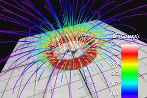
 Ted Yapo
A Tesla is 10,000 Gauss. The earths field is about 0.5 Gauss. The magnetometer arrays use nanoTesla (nT) as their unit. Sounds better than microTesla.
So 16030 nanoTesla is (16030/1,000,000,000) Tesla or (16030/1,000,000,000) * 10,000 Gauss
All those zeros (16030/10^9) * (10^4) = 16030/10^5 = 16030/100,000 Gauss = 0.1603 Gauss
The field is a vector quantity. It has three separate readings for North, East and Vertical. You can find the total by
TotalField = sqrt(BN^2 + BE^2 + BV^2) where BN, BE, BV are the magnetic field in North East and Vertical directions. Unfortunately most magnetometers reference to the direction of strongest reading - the magnetic north direction, which constantly changes slowly over time and moment by moment by tiny amounts.
Perhaps you can think of a way to assemble three orthogonal (mutually perpendicular) coils. The small signals over time induced by changes in magnetic field will give a small voltage. But it is hard to measure. If you floated a magnetic needle in a fluid at neutral bouyancy and then kept it precisely directed using three magnetic field coils, you could measure the field elements. You can make a simple three axis magnetic field by pairs of solenoids (coils) with gaps. Think of a small cube and then a coil for each face. And a way to take it apart to put something inside. So a flat plate with a cylinder for winding the coil.
What I first read your title, I thought you had gone a step further and found a fabrication facitlty or tool that could print conducting traces on a PCB board. We use coils of wires beause they are moderately easy for human hand assembly and machine assembly. But a spiral also has a field. You just google "spiral coil" "magnetic" ("gauss" OR "Tesla") and that should get you close.
I just checked and there are, indeed, some examples and links to calculations..
So six of these spiral printed PCB boards would create a magnetic field in a volume that can be precisely calculated, then calibrated. It need not be a smooth curve. Squares, triangle, octagon, zig zags or random conductors - as long as they conduct current - will have a magnetic field.
I wanted to make a three axis magnetometer and was thinking of printed conducting trace coils. Let the PCB people print it precisely. Determine and later measure the current and its variations,and try to see if you can makes sense of the readings for your location.
There are many "magnetic field at my location" calculators. Here is one from the Canadian government. https://www.geomag.nrcan.gc.ca/calc/mfcal-en.php
Enter the date, latitude and longitude. You can go to google maps for your location and click on your house or lab or location. The latitude and longitude in decimal degrees will be at the top of the page. This particular one cuts off at 2020, so is getting out of date.
Here is a calculator for National Centers for Environmental Information at NOAA.gov
https://www.ngdc.noaa.gov/geomag/calculators/magcalc.shtml#igrfwmm
I always have to stop, put myself in Greenwich England and then look toward my location. I live in Texas and standing in Greenwich at the "prime meridian" ( I would just call it "zero longitude", who the heck wants to memorize those odd names.) and then look West toward my house. Or East toward Russia.
SuperMag has lots of stations. You can see this with Tucson Arizona already selected. At the top click Plot Data or View Data. Today it is nearly flat and the Red (East), Green (Z or veritical) and Black (North) components of the field are hard to see. Click "Do Not Remove ANY Baseline" on the left to see the raw data.
Hope the helps a bit. I like your printed form for coils. But for three axis work, I think I would use six coils. Think one inch pieces of paper towel cardboard cylinders stuck on the six sides of a cube. You are doing the right things. I envy you. I have no space or tools to make things easily.
I will see if I can sort out the Bloch (or Maxwell-Bloch) equations for magnetic resonance where you use three orthogonal (mutually perpendicular) magnetic fields. All the magnetic resonance gets really complicated to sort out, because they could only afford a single axis. With low fields and three axis, when you drive all three axes, the field you create interacts with the earth field and changes the voltage and current in each coil from if there were not external field. It is tiny, but with fast analog to digital tools, you can get a LOT of data points. I have used cheap usb microphones and oscilloscope software. Or just used HTML5 and measure the "acoustic or sound" data. Almost the same price are Software Defined Radio dongles that can measure up to 1.8 Gigahertz. But you want to find the ones that can measure down to zero frequency.
Looking at https://www.sciencedirect.com/topics/engineering/bloch-equation I think that a three axis set of equations would involve tracking the voltage and current in each coil, while trying to adjust the current in each fields so that the voltage of each coils stays zero. Then use the actual current to calculate the field you produces to null the earths magnetic field, and any other ones around. Just ADCS and data collection. But you need coils.
If you just took three of your coils and wound them close to the same. The earth's field is so large that they would not all have to cover the same volume. Just be mutually perpendicular ("orthogonal"). But they won't pick up much if the field is not changing, or the coil not moving. So could you use a piezo on each coil and make them move at a convenient frequency, and the use that frequency to repeat your readings of current and voltage for each coil as a function of phase? With SDRs you get millions of samples per second. And a sound wave is only a few hundred or thousand Hertz. So you make many readings per cycle.
Sorry to write so much, but I collect all this kind of stuff, but never get to use it.
It might be worth trying to make a three axis low field magnetic resonance proton magetometer. Just put water in the cube.
If you want to use the Maxwells equation, you might want to focus on "Auxiliary fields, polarization and magnetization" But they let anyone change things so tomorrow it might says something completely different. An encyclopedia is NOT suppose to change everyday and new people are not suppose to play with things that work.
https://en.wikipedia.org/wiki/Maxwell%27s_equations#Auxiliary_fields,_polarization_and_magnetization
None of these equations (I cannto write them here or include image clips or links) is really in a useful form. I will just remind you that the curl is the same as "circulation" or "vorticity" and measure fluid rotation. A fairly clean version of the way to calculate it is at https://en.wikipedia.org/wiki/Curl_(mathematics)#Usage
I like the one that has shows the X Y Z components. In B terms that is
(dBz/dy - dBy/dz) in the X direction
(dBx/dz - dBz/dx) in the Y direction
(dBy/dx - dBx/dy) in the Z direction
Probably not much use, but these are the pieces and things I would look at if I had time to make a three axis, low field, magnetic resonance, proton magnetometer. But I would start by having three orthogonal coils and just monitor the heck out of them - current and voltage with lots of samples to gain a better understanding of how the data looks over time.\
Richard Collins, Director, The Internet Foudation