Close
0%
0%

vapsy

A tiny vapor phase reflow oven

Similar projects worth following
Up front: don't build this without a proper control system. A vapor phase reflow oven involes liquids and steam (!) at temperatures up to 230 °C. Even more around the heaters and when things go wrong. See https://hackaday.io/project/7495/log/26044-geyser-mode-this-thing-needs-more-safety-measures.

Vapsy is a tiny vapor phase reflow oven I built using basic machining (milling, lathing) skills. The why:

1) I failed at reflowing a 0.35 mm pitch BGA in my infrared/convection oven;
2) a quick look at my and my colleagues' drawers revealed the following:
An Aluminium block with already drilled holes for 4 heaters, heaters with 100W each, tons of thermocouples, and some galden leftovers.

I decided to give it a try!

I wanted the oven to be/do/have:

  • small
  • transparent lid. I like to see what's going on in there
  • keep the amount of escaping galden as low as reasonably possible
  • galden that escapes the chamber should be trapped in such a way that it flows back to the heater
  • shouldn't look like a frankenoven

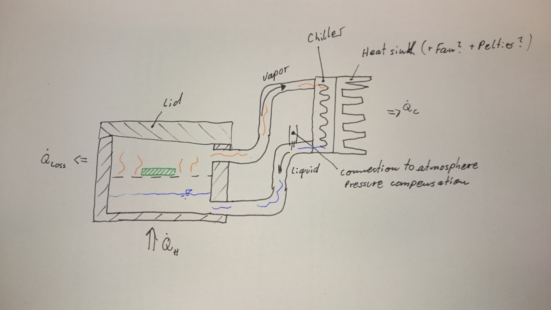
The implemented design resembles the idea outlined in this diagram:

Evaporated galden can flow to the external chiller, where it is cooled down by convection (forced convection on the inside and natural convection on the outside). The chiller is simply a piece of wound steel pipe with brass fittings brazed on:

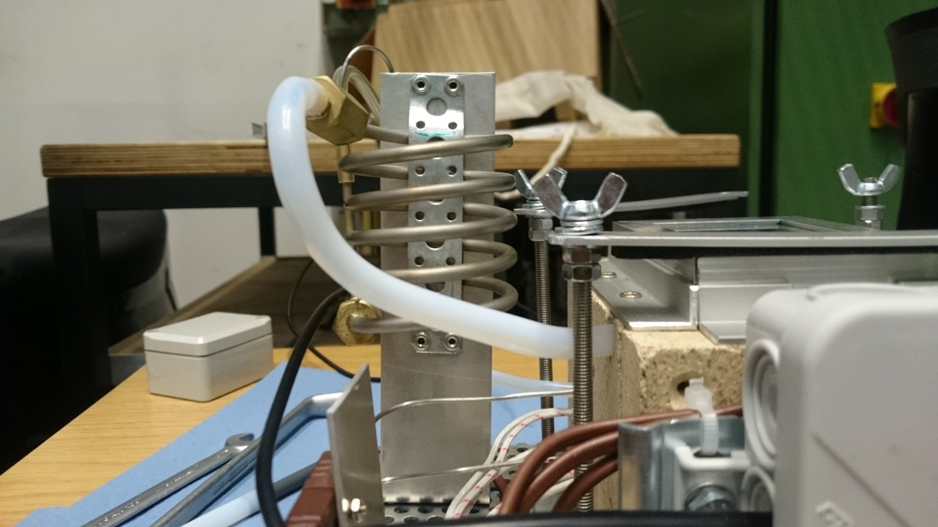
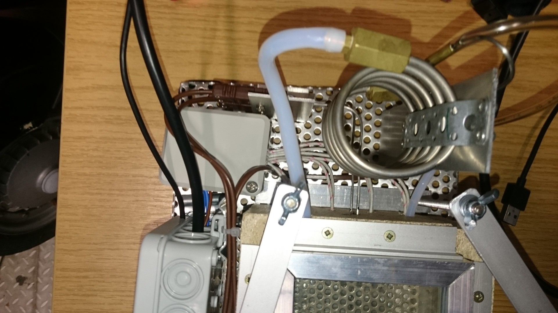
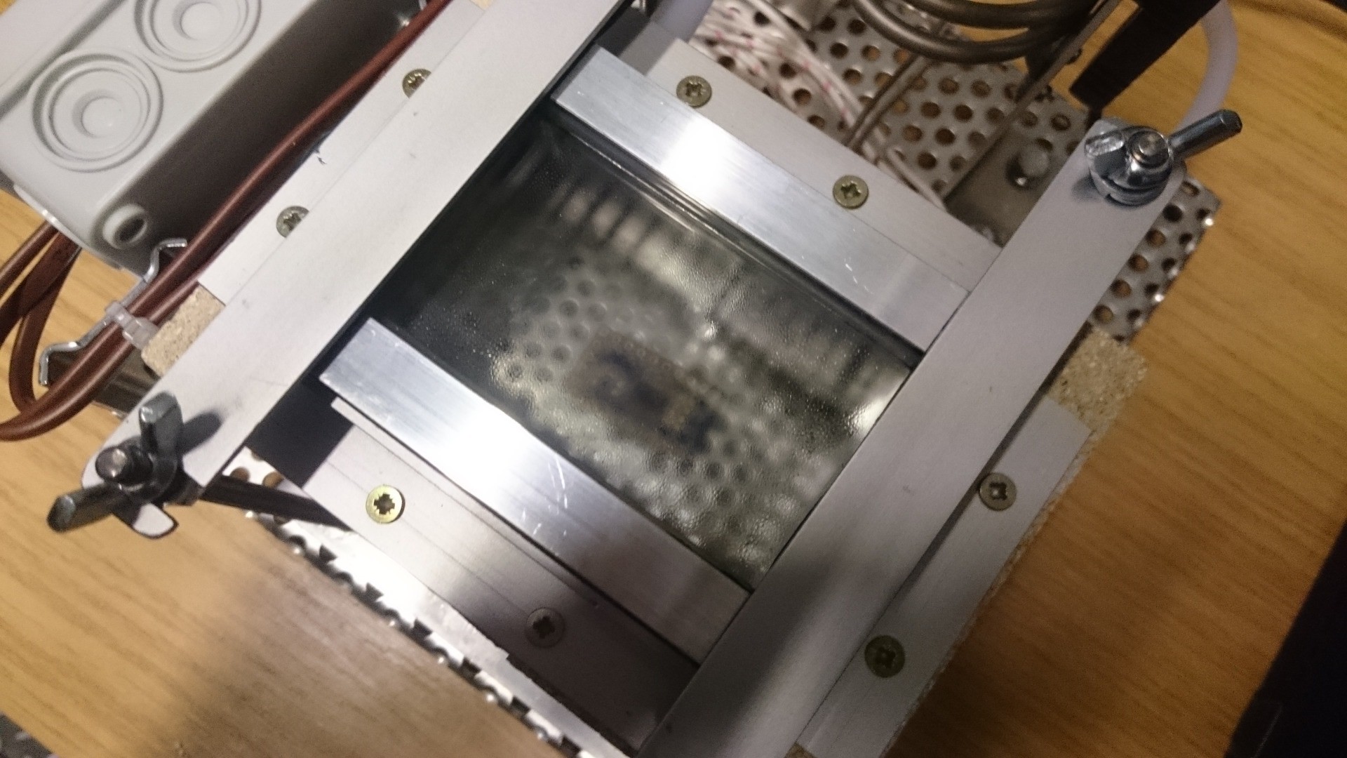
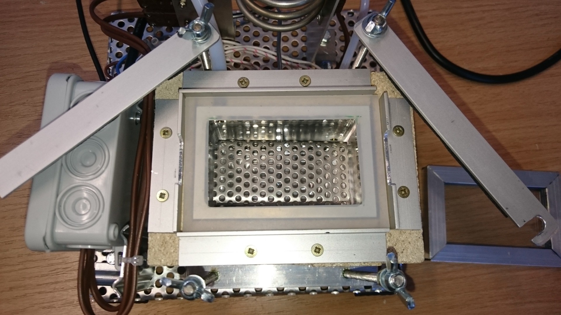
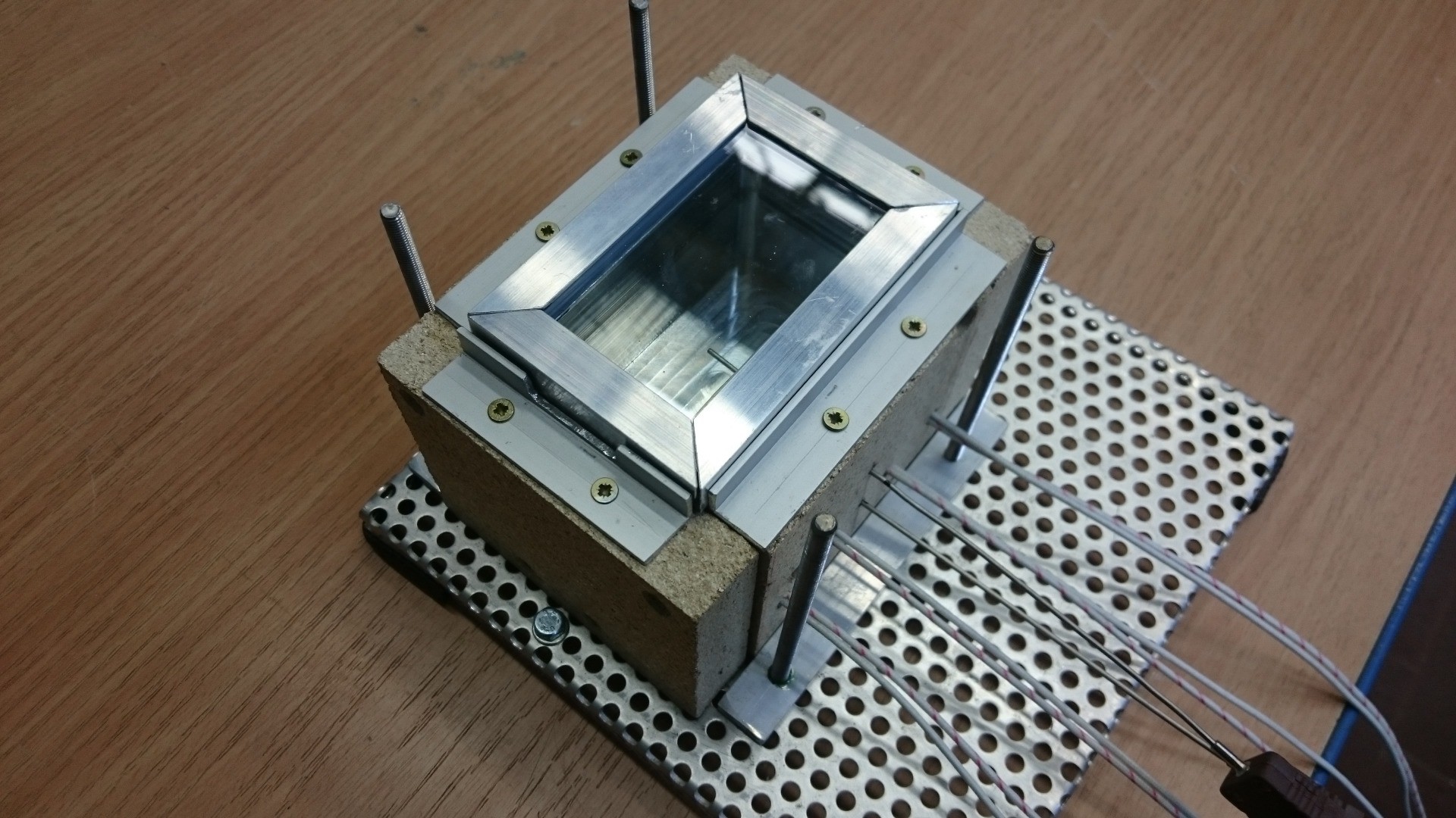
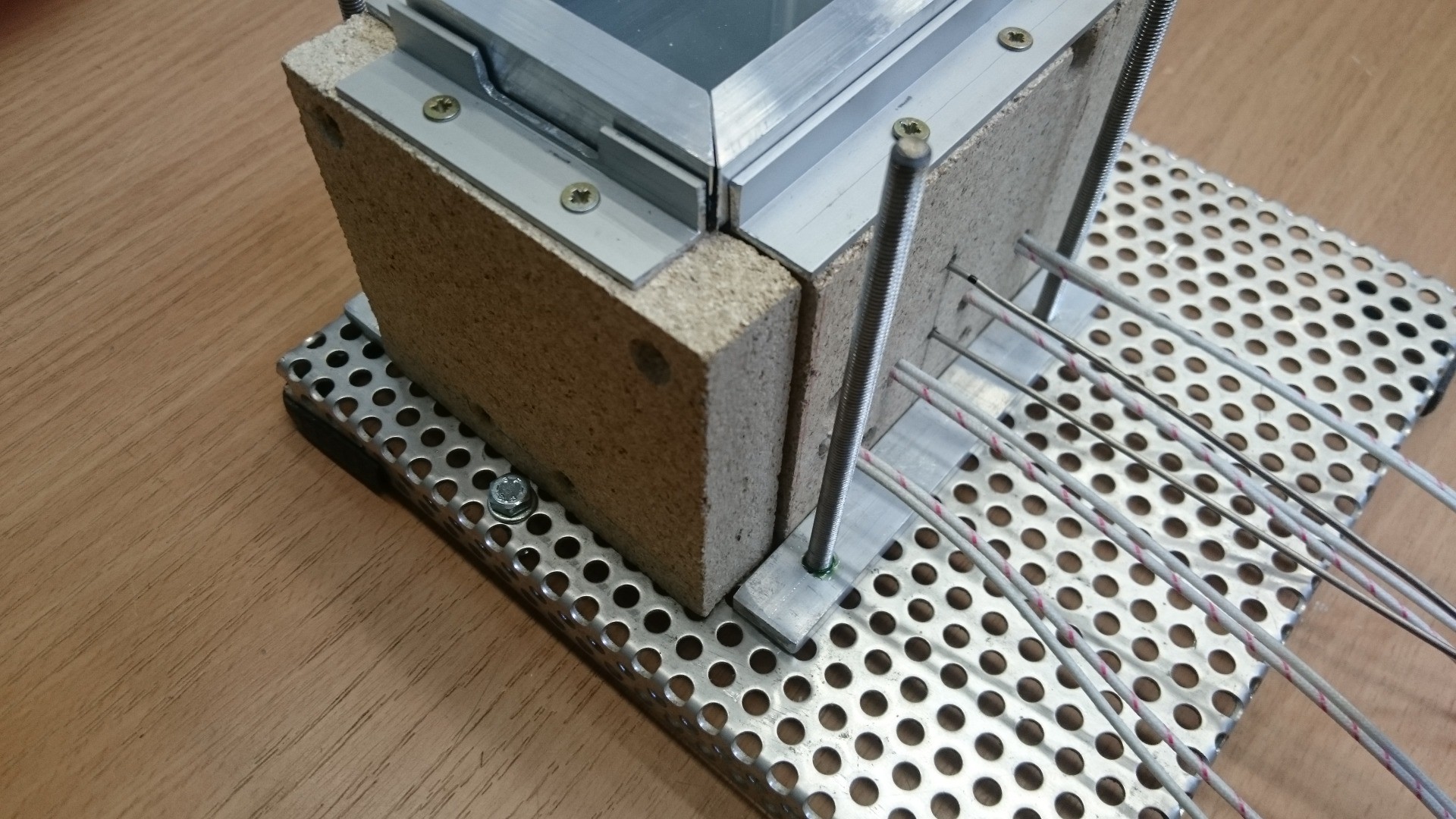
This is the base with chamber, heaters and insulation:

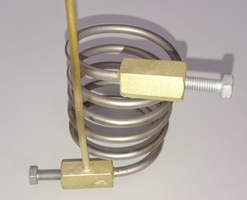
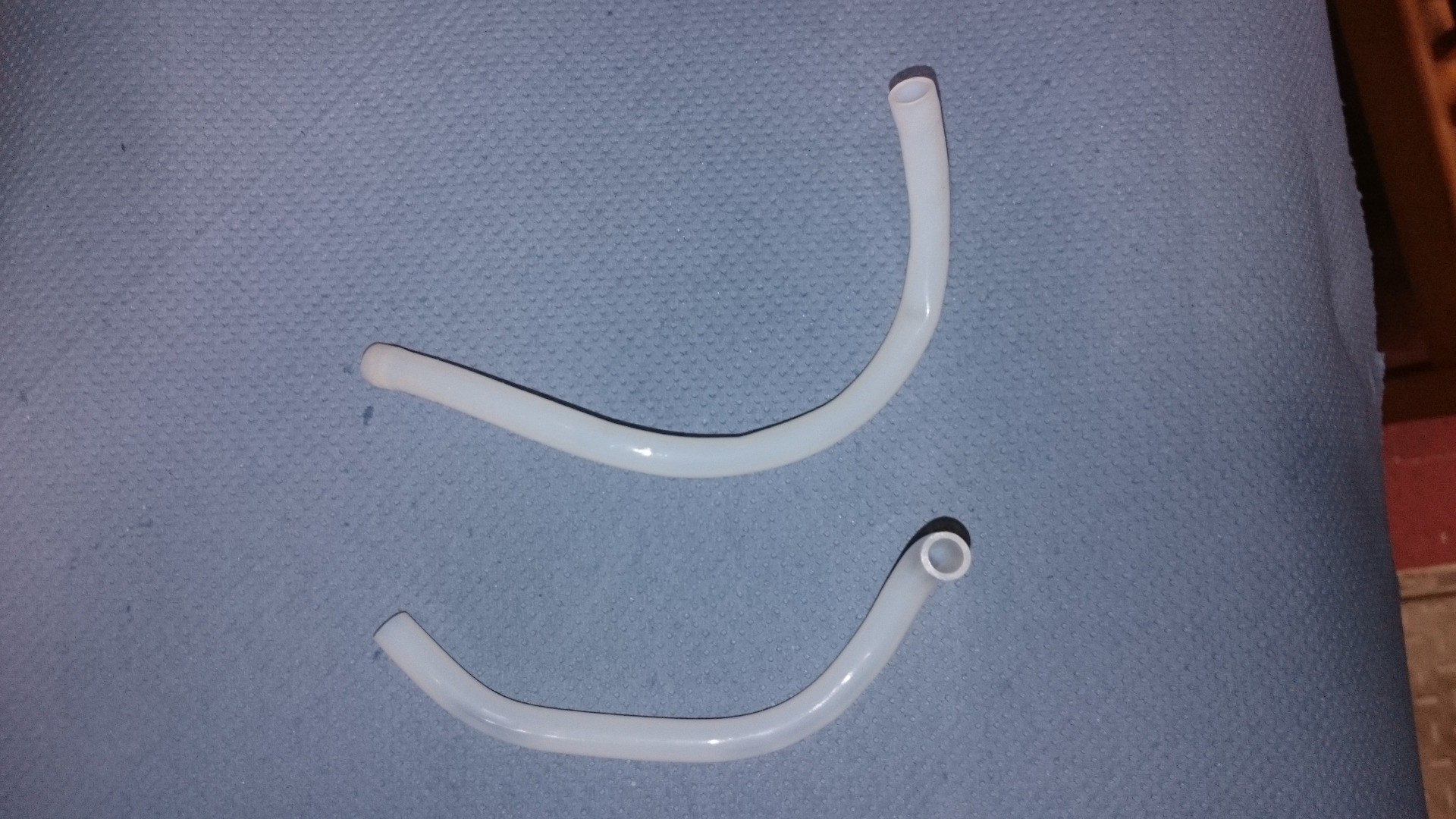
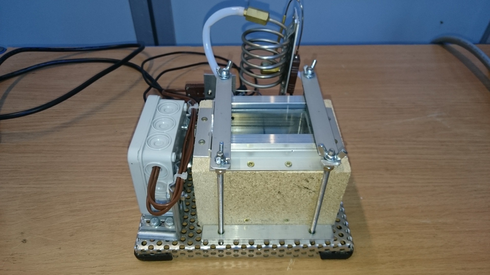
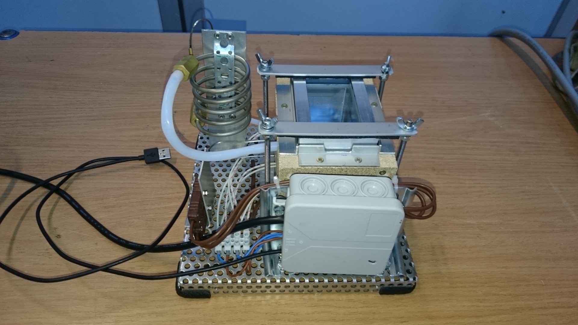
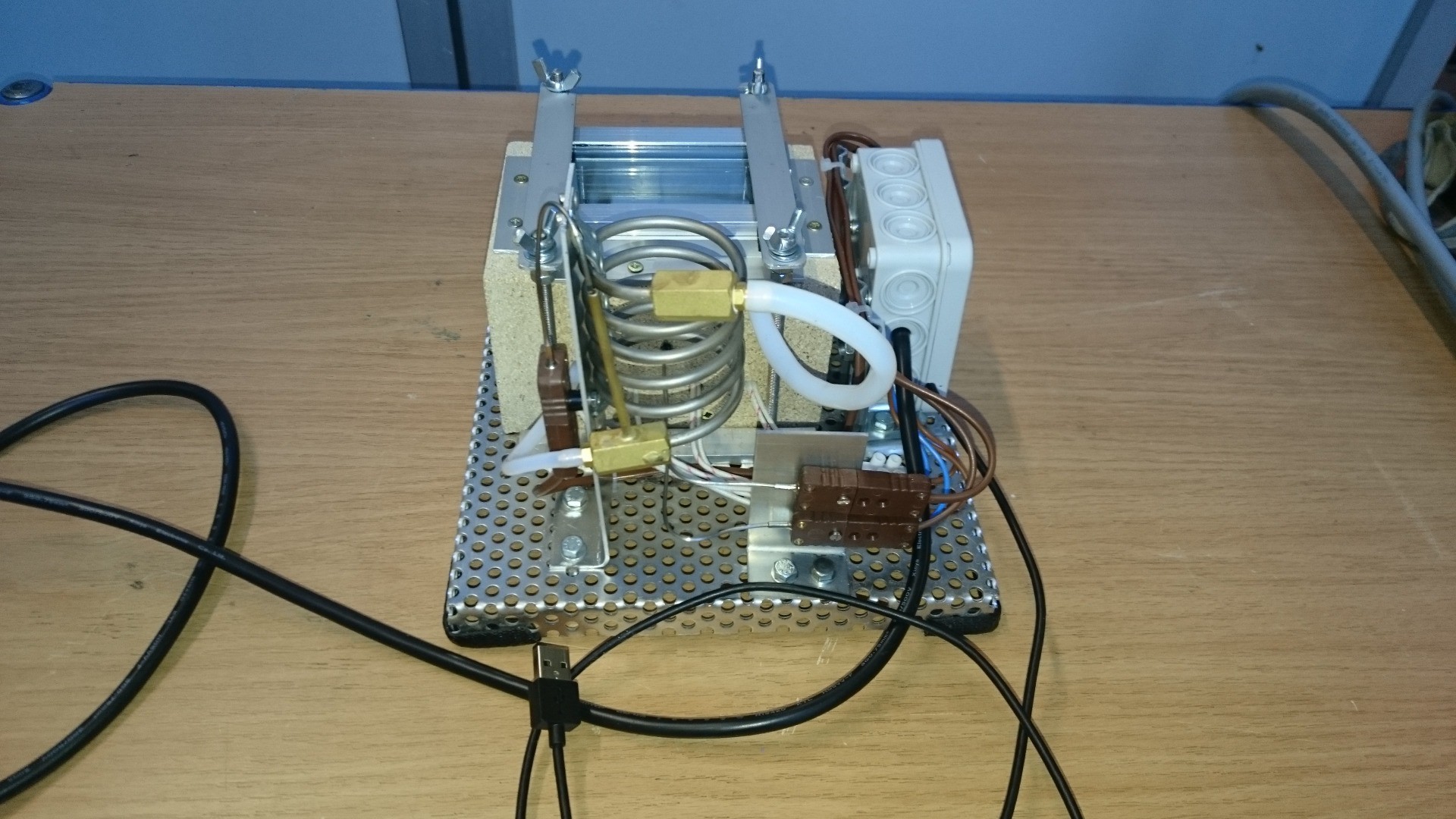
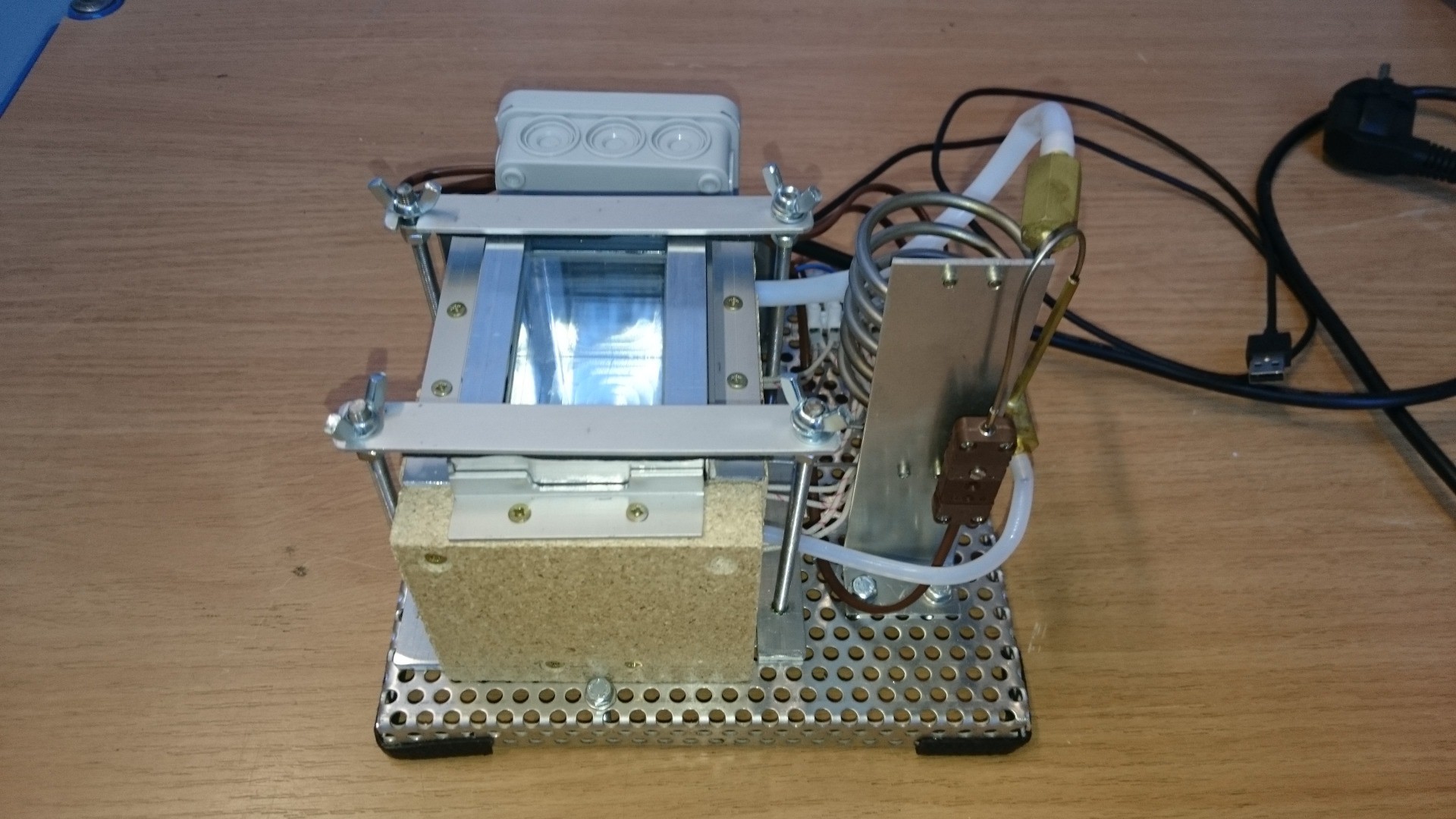
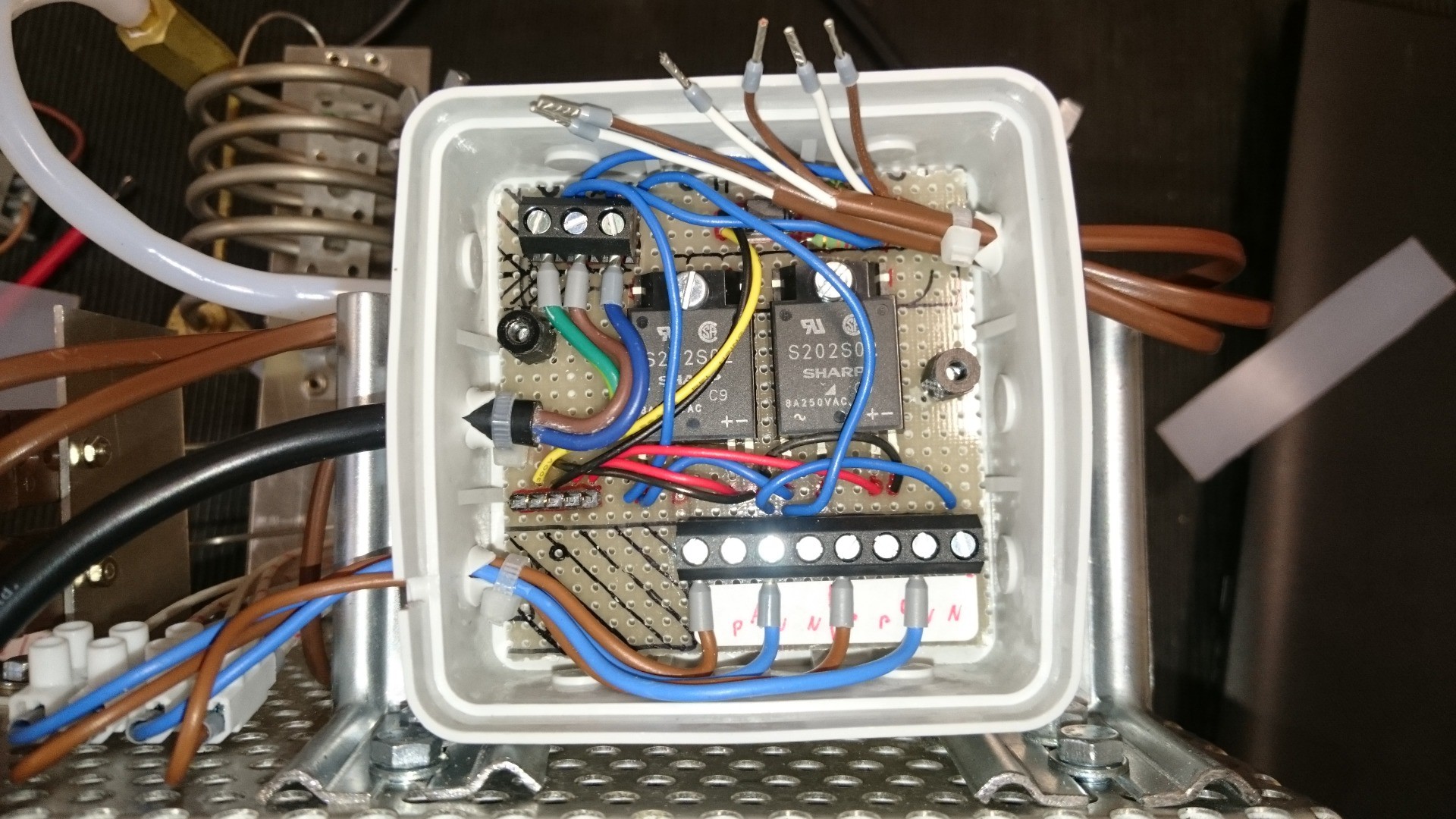
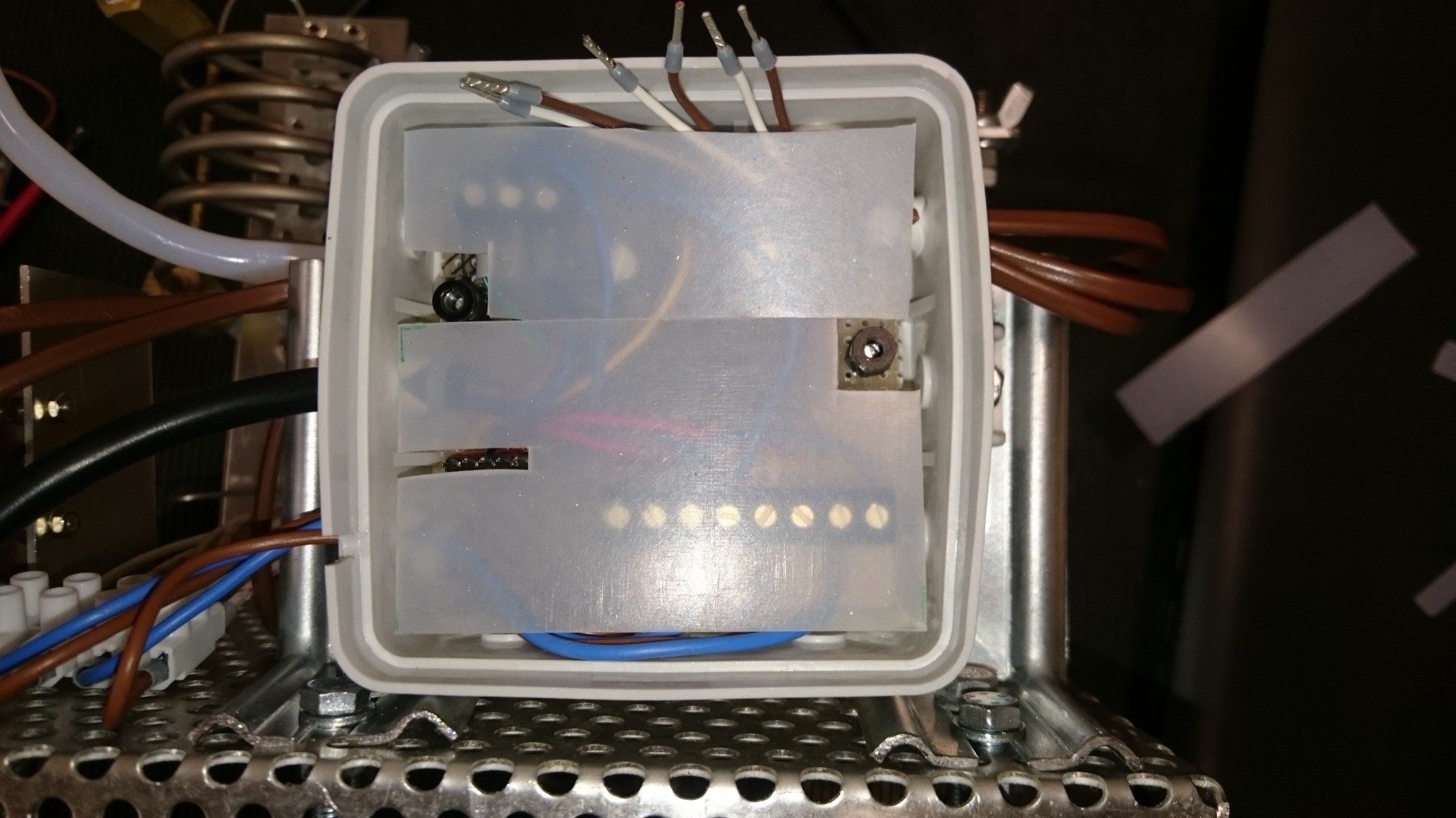
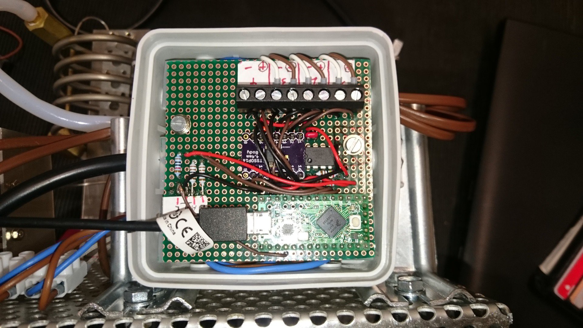
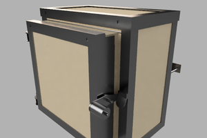
Final assembly with lid, tubes between chiller and chamber, and electronics box:

The whole thing will have some heat losses through the lid and insulation, so some of the evaporated galden will flow right back along the walls or through the vapor tube. Galden that evaporated above the heaters will not flow through the liquid tube because there is no driving force in that direction; the evaporated galden will be driven upwards by buoyancy instead. If the lid does a good job at sealing the oven, I'll also need a pressure compensation between the oven and the atmosphere, which should be on the liquid side.

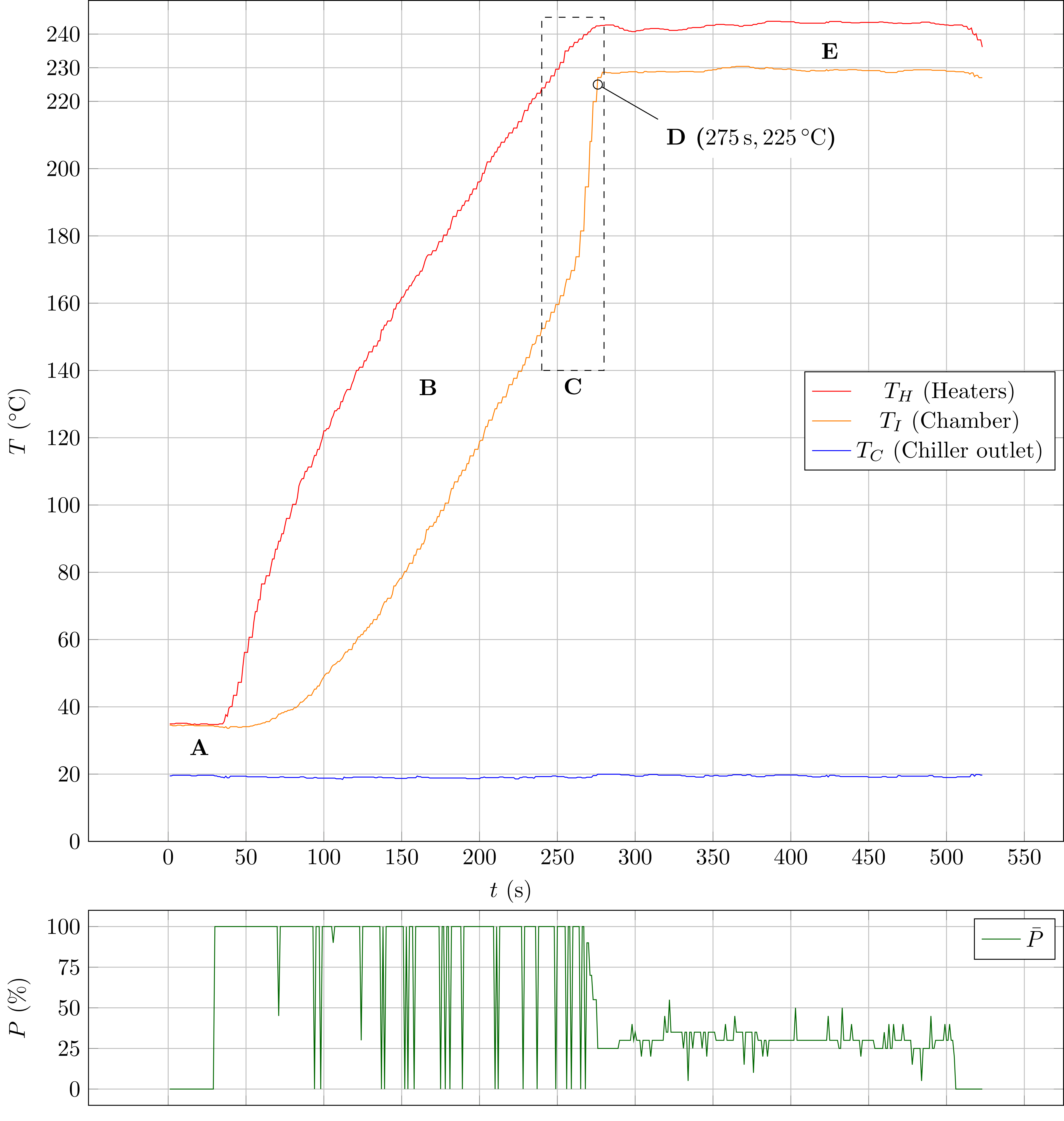
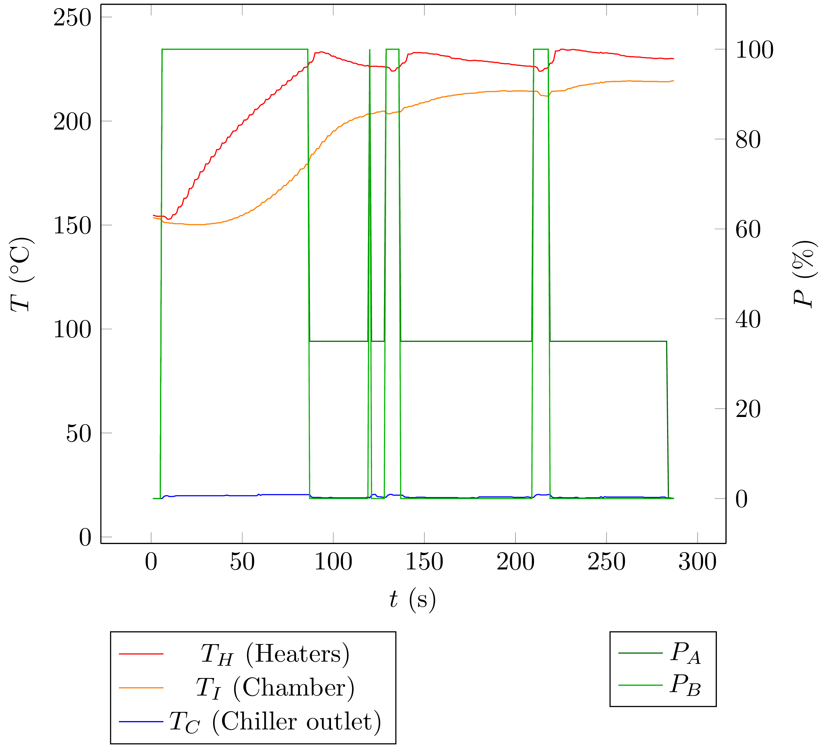
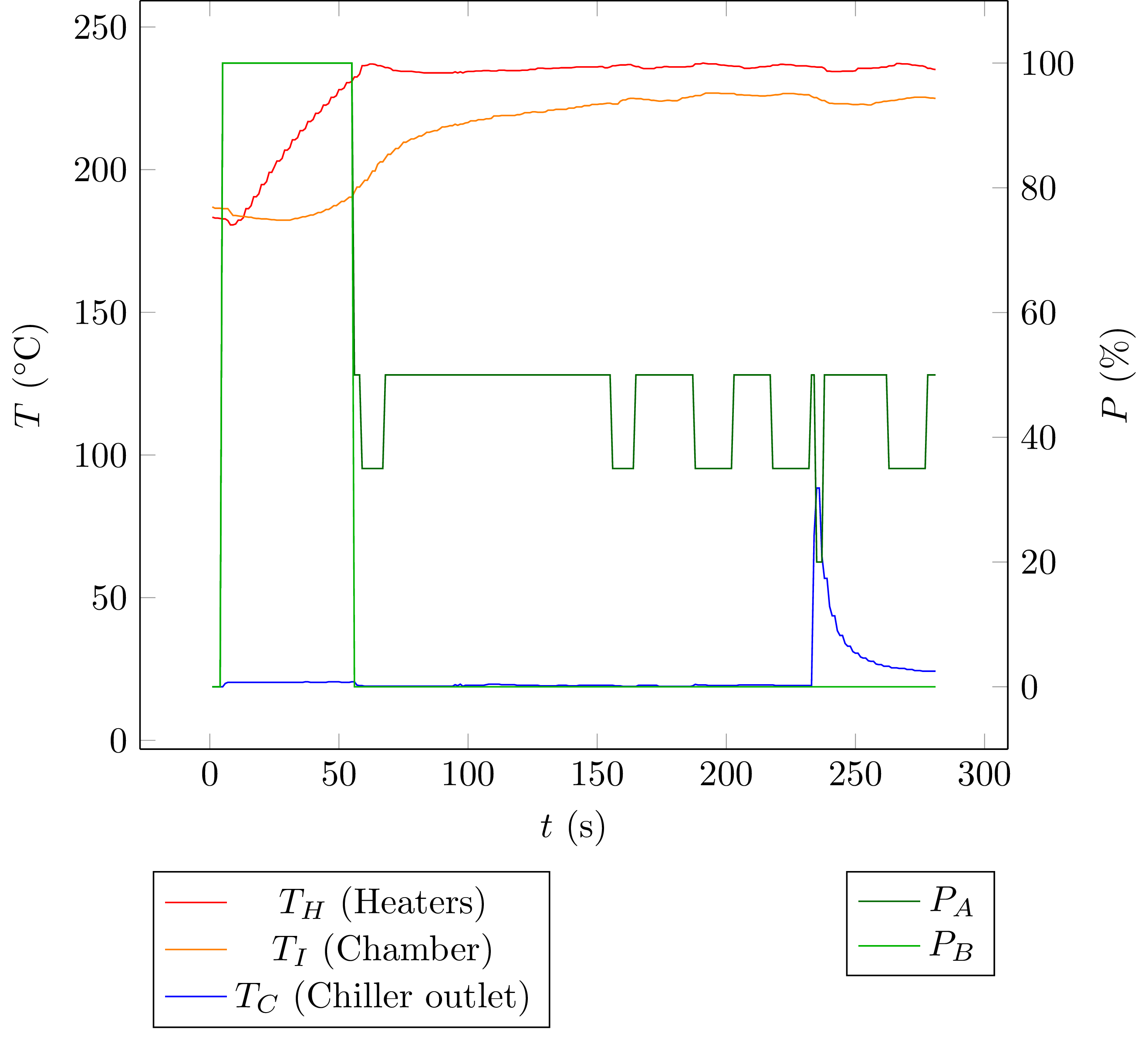
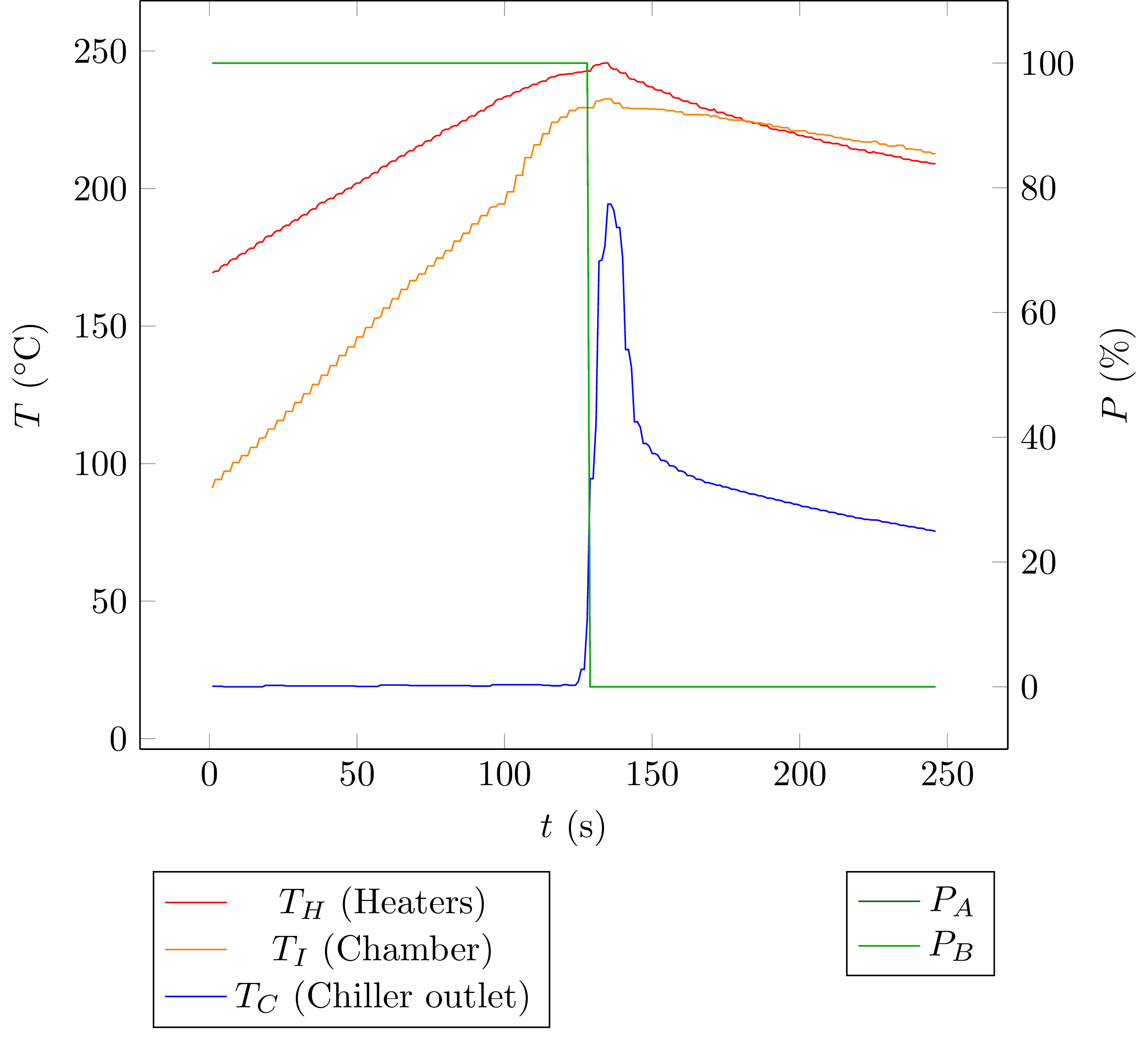
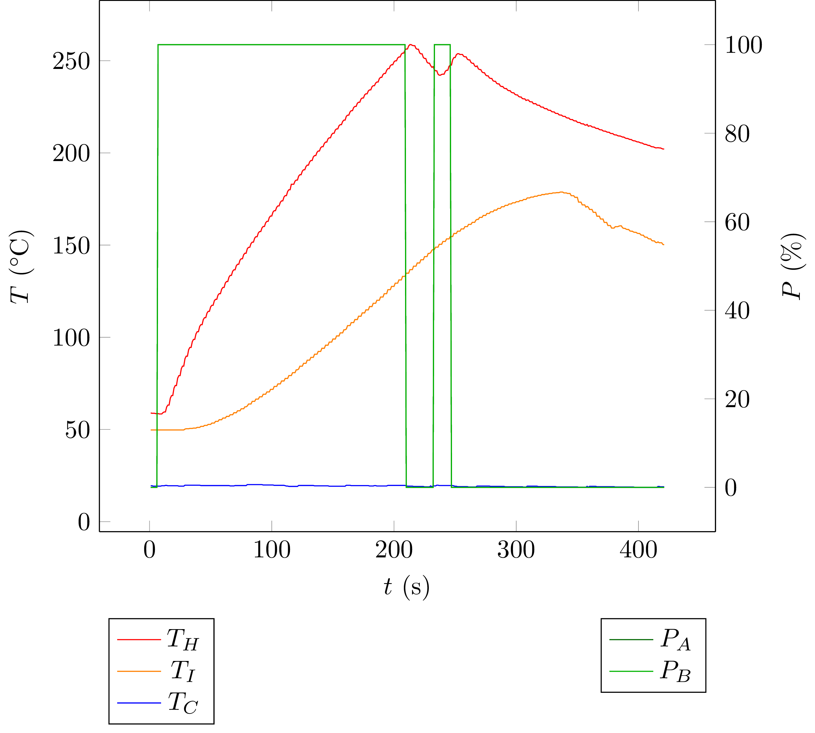
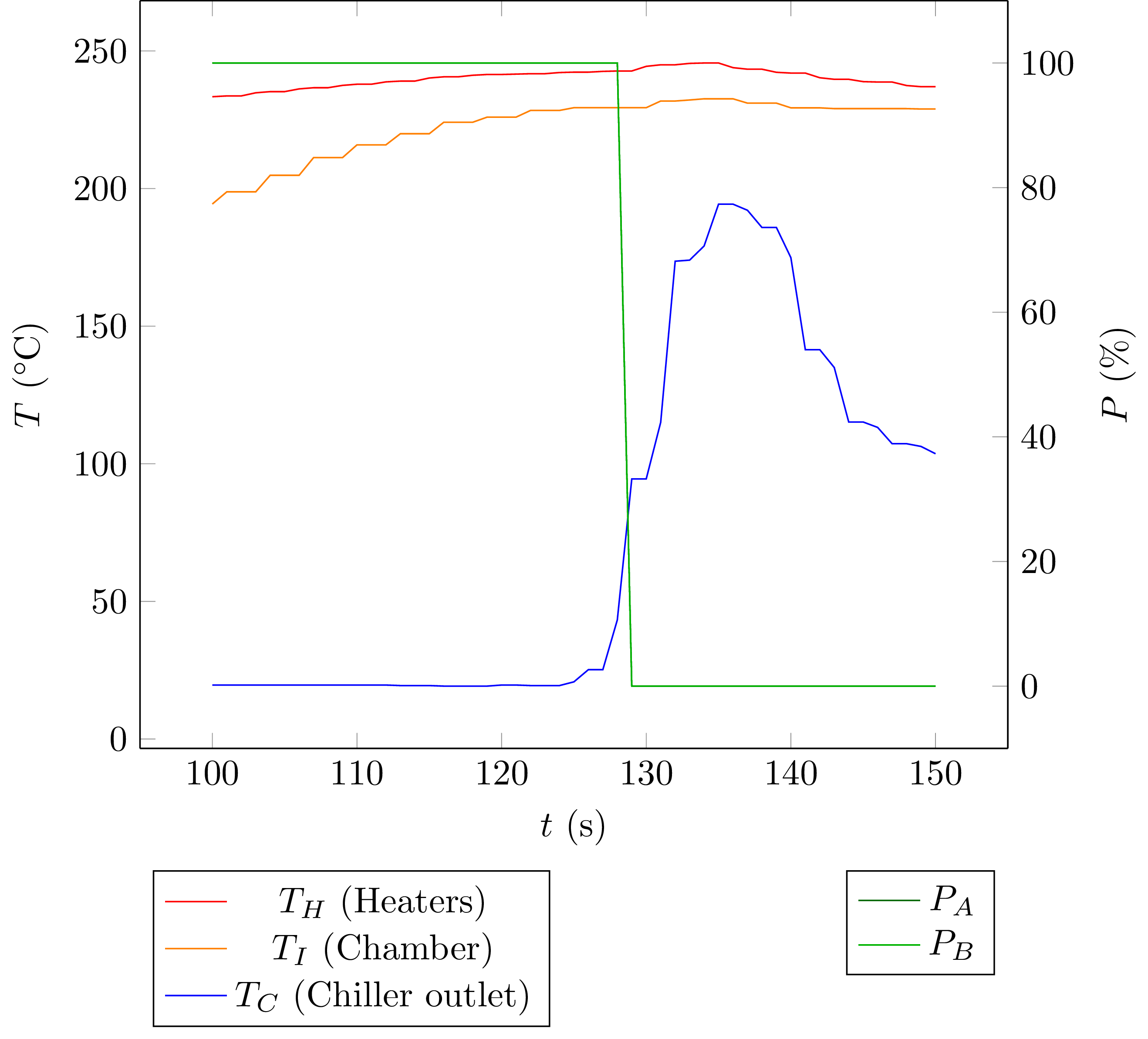
While galden evaporates, the chiller has to dissipate the amount of heat that was needed to evaporate the galden. While that is the case, the oven has a cozy reflow temperature that matches the evaporation temperature of the galden.

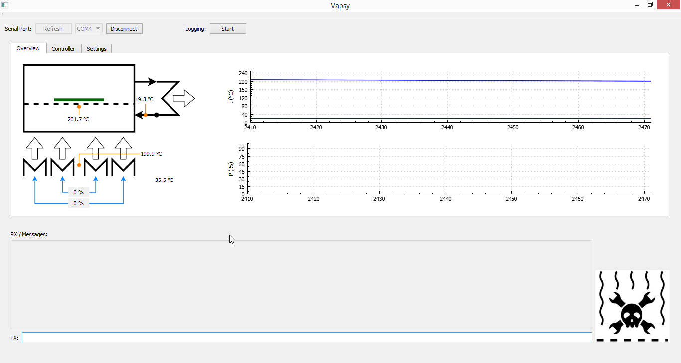
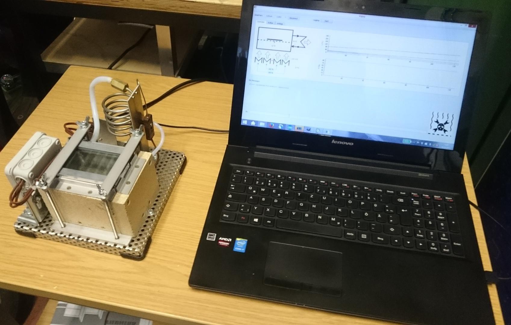
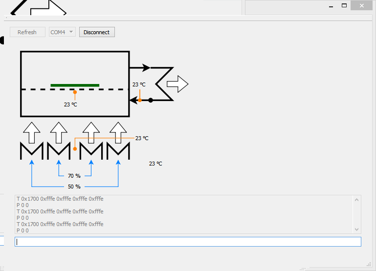
Of course, I also needed a GUI. I chose Qt for that because it now has a serial port class, which makes the code quite portable. It's not finished yet, but it will eventually end up on github. Here's a screenshot of an earlier version:


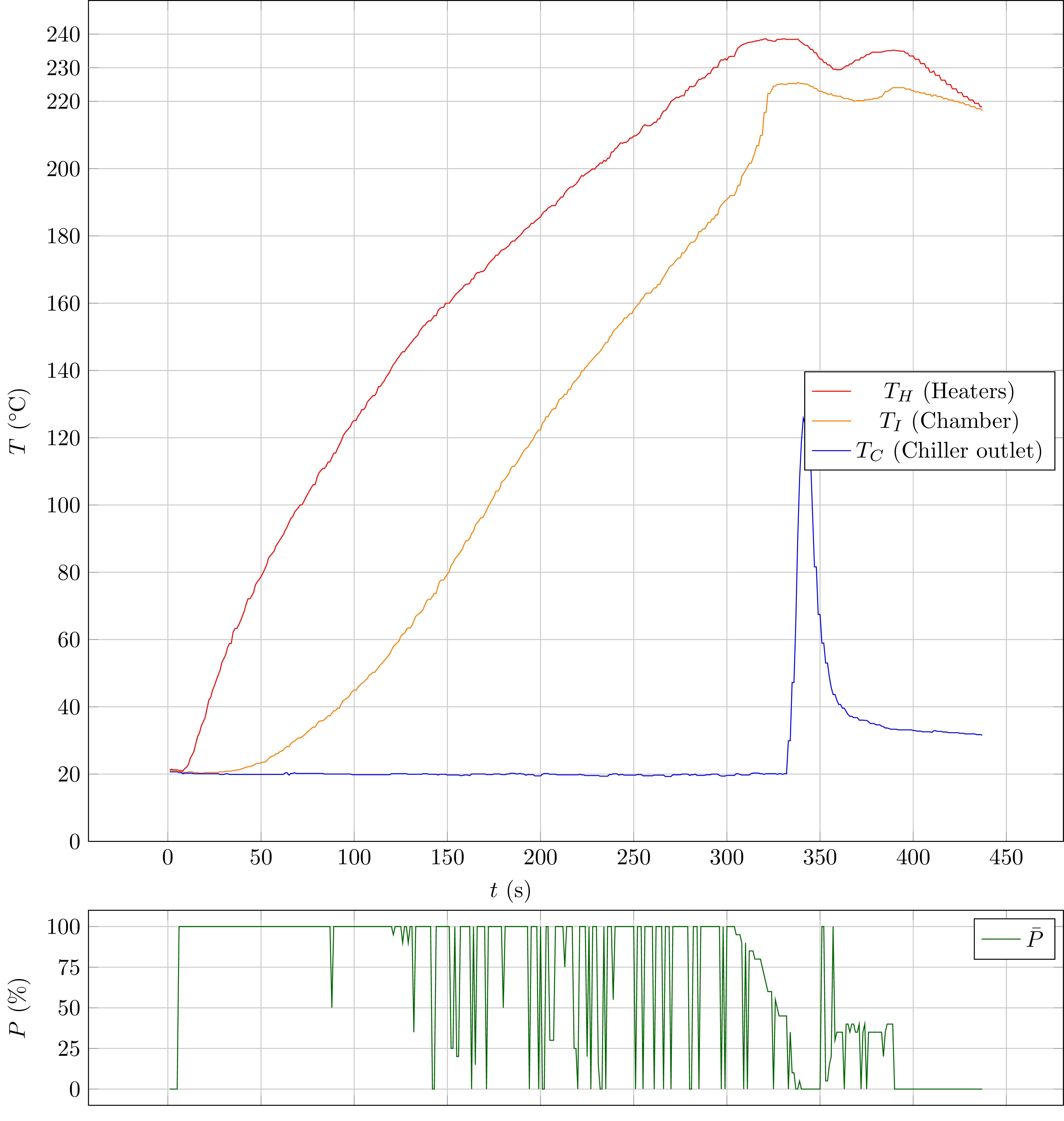
It turned out that the oven doesn't exactly work as intended, but it does solder PCBs. Check out the project logs for details on every step of the build!

  • 1 × power supply for the Teensy, Peltier, other stuff
  • 1 × MCP3428 Data Converters / Analog to Digital Converter ICs (ADCs) for the thermocouples
  • 1 × DS1621 Sensors / Temperature, Thermal Cold junction compensation
  • 1 × (optional?) external galden chiller A simple piece of brass pipe will do
  • 1 × Reflow chamber Aluminium block

View all 10 components

  • Well it's still not perfect, but it solders - so...

    Christoph11/15/2015 at 23:22 0 comments

    Here's the latest data (from october 20th to be honest):

    Until about t = 330 s everything is fine, the galden is slowly heated, starts to evaporate and finally the chamber is filled with saturated vapor. As soon as excess galden flowing through the chiller reaches the chiller outlet thermocouple, the temperature at that location suddenly rises. The safety code kicks in and disables heating. Another very important thing happens now:

    During the heating phase, small amounts of galden vapor condense in the chiller inlet and build a liquid drop in the teflon tube. When more galden vapor enters the tube, this liquid (now cooled down by the ambient air around the tube) is pushed back into the chamber and suddenly cools it down. This can happen for two reasons:

    • The chiller inlet tube goes upward from the chamber to the chiller. Any galden condensing in the tube will flow back towards the chamber.
    • The fitting between the chamber and the chiller inlet tube has a small inner diameter (about 2 mm I'd say). This prevents the galden from actually flowing back into the chamber, so it can block the tube instead.

    After that the chiller outlet is slightly warm, and the control code can start saturating the chamber again.

    This intermittent flushing with cool, liquid galden prevents the oven from operating how I intended it to. But it does solder PCBs, so I'll call it good.

  • Works well!

    Christoph10/12/2015 at 19:22 0 comments

    After some bug fixing in my controller code and retuning, I got this plot of a heat up phase and some time in "evaporate some galden" mode:

    A) Oven starts slighty warm at about 35 °C, because it didn't cool down completely from the previous run. Things start at t = 30 s.

    B) Heating up the chamber to 225 °C before switching to evporate mode in the region marked as "C".

    C) When the heaters reach 230 °C, galden starts to evaporate at the chamber's bottom, drastically increasing the heat transfer rate. The galden vapor pushes out the air from the chamber until it is filled with saturated vapor. The chamber temperature then doesn't get above 230 °C as long as there is liquid galden at the bottom.

    D) The chamber reaches 225 °C and the controller switches to evaporate mode.

    E) A pretty much constant flow of galden is evaporated and cooled down in the chiller (I could see galden bubbling up the chiller inlet tube). The chiller outlet temperature doesn't rise, though, because the mass flow rate is very low. The heaters are kept at 243 °C.


    So I tried to solder a #DIPSY which worked out quite well (it seems):

    I could measure a resistance of some 16...20 MOhm between all pins and ground or supply.

    One problem was the bottom side which I assembled manually, and I ripped off one trace while soldering the capacitor. It was possible to replace it with a piece of wire:

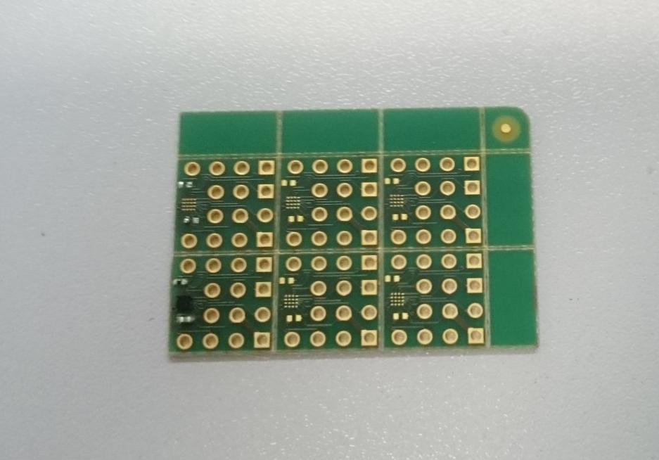
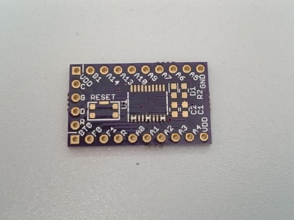
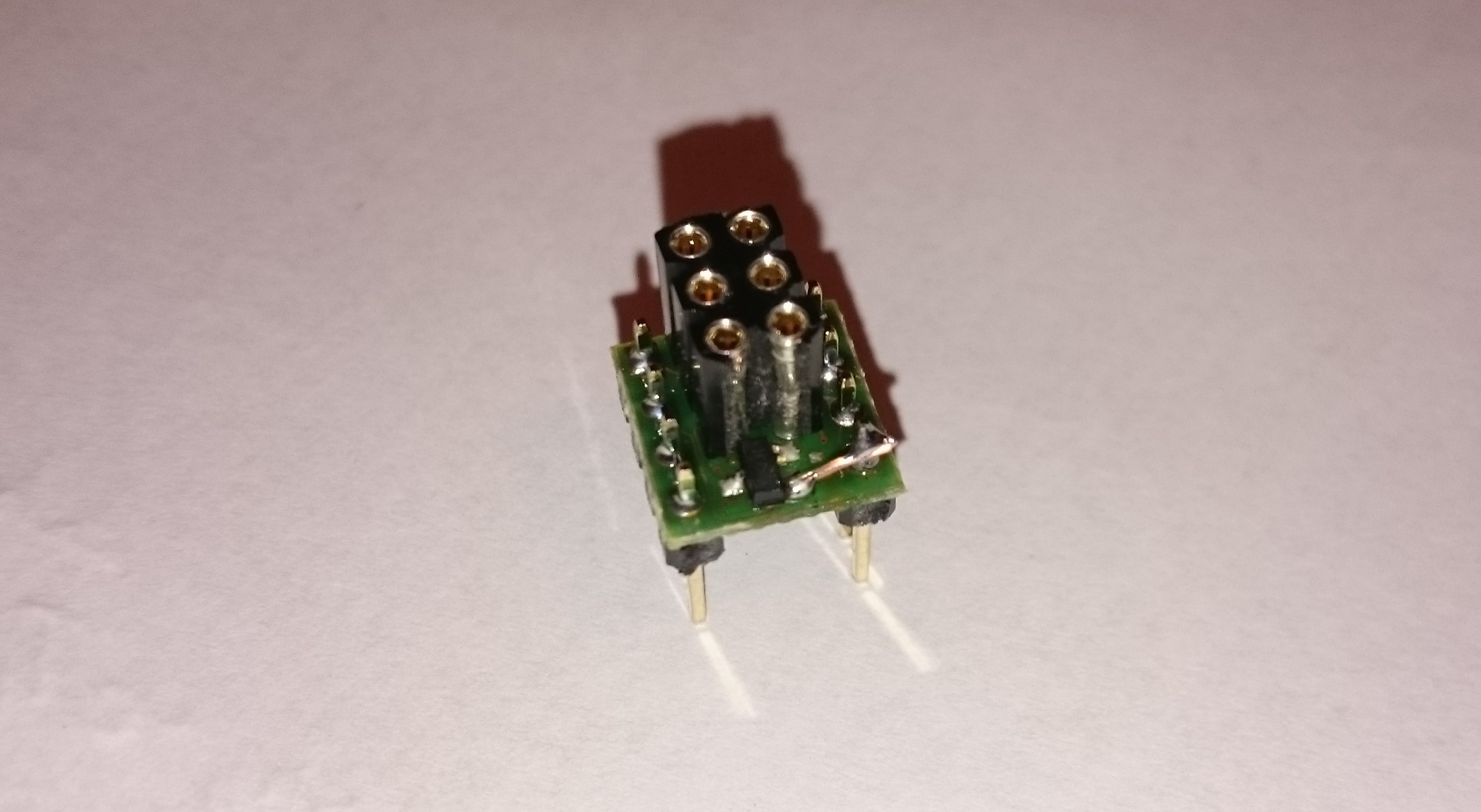
    Until now the only consequence of this is that I had to turn the pcb around, so the pins are mirrored.
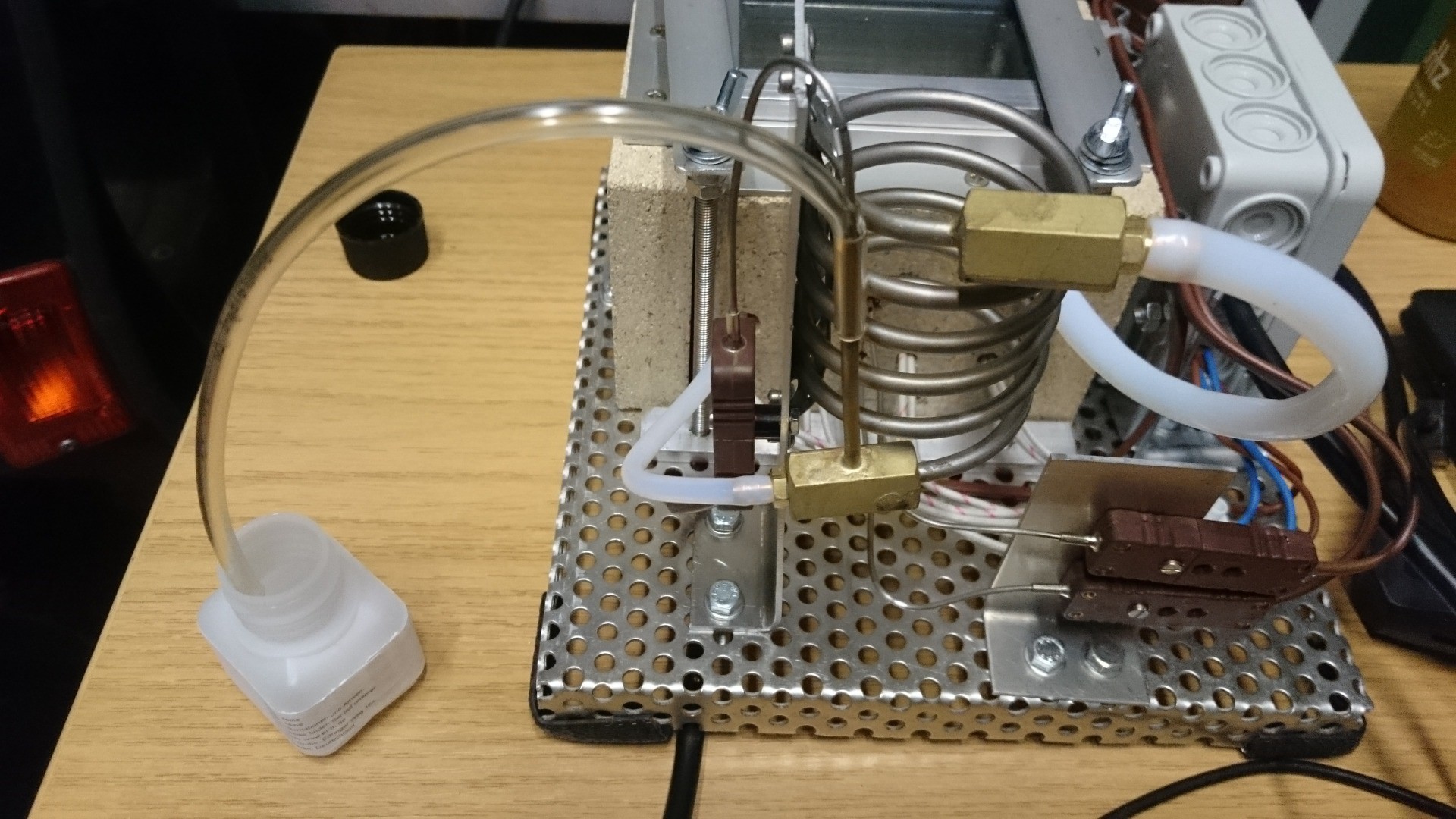

  • Some hardware tweaks

    Christoph10/08/2015 at 11:32 0 comments

    First of all I installed a piece of tube to catch excess evaporating galden:

    It has an extra hole in the bend for the thermocouple. I don't know what material that is but it shouldn't get too hot.

    The next thing was the tube between chamber and chiller inlet, which allowed quite a lot of liquid galden to add up in the horizontal section near the chamber. Here are the old tube (above) and the new one (below), the inlet section to the left:

    The new one is shorter and has an extra bent close to the chamber. This is how it looks when installed:

    Much better than before!

    And at last I have a small box for the heaters' terminal strip:

  • Another test with different thresholds

    Christoph10/08/2015 at 07:13 0 comments

    Some more threshold temperature checks were implemented (my plan was different but I had an error in the implementation. The power should be higher, and these are the actual values):

    • limit power to 70 W (17.5 %) when the heaters are above 225 °C
    • limit power to 40 W (10 %) when the chiller outlet is above 70 °C
    • cut power when the chiller outlet is above 100 °C

    This is the result:

    It's obvious that the lowered power isn't enough to compensate for losses through the insulation and evaporate more galden. Some more galden is evaporated, but the slowly rising temperature in the chamber indicates that there's still not saturated vapor in there, but an air-vapor mix below 230 °C. If it was saturated vapor it would have the evaporation temperature of 230 °C.

    So I changed this a bit:

    • limit power to 100 W (25 %) when the heaters are above 230 °C
    • limit power to 70 W (17.5 %) when the heaters are above 235 °C
    • limit power to 40 W (10 %) when the chiller outler is above 70 °C
    • cut power when the chiller outlet is above 100 °C

    Things were a bit different now:


    Now there's saturated vapor in the chamber at about t = 220 s, and a short while later the chiller outlet temperature jumps to some 90 °C. This jump could be anticipated, because some evaporated galden condensed in the chiller inlet tube, which has a short horizontal section just behind the chamber. A galden drop built up here, basically obstructing the outlet until too much galden evaporated and suddenly a lot of it got into the chiller.

    The chiller reacts quickly to the increased galden mass flow, and also shows fast recovery from such a "flush".

    Next:

    • improve tube geometry to have less galden being collected in there. This is annoying because the teflon tube is so hard to get into shape;
    • fix power setting algorithm,
    • write a P- or PI-controller for the heating up state, and one for the saturated vapor state.

  • Deriving some thermodynamic properties of vapsy

    Christoph10/01/2015 at 14:16 0 comments

    On my way to a better control strategy I took a closer look at the plot from yesterday. I'm interested in estimated heat capacity of the chamber and the isolation, and some sort of heat transfer coefficient between the oven's inside and the ambient air.

    Here's the plot again:

    Heating up:

    (index h)

    The chamber's temperature rises at about 0.82 K/s, with the heaters at 400 W. At the same time, some heat will be lost to the ambient air. This rate depends on the temperature difference between heaters (let's say at t = 95 s) and ambient air, and also depends on the oven's heat capacity C:

    Applying the first law of thermodynamics to the heating process gives

    That's one equation with two unknowns. We need another equation to solve for them. Also note that I'm using the heaters' temperature here because the chamber is made of aluminium, and it will have a more or less uniform temperature. This is probably a better choice than using the chamber temperature, but that will come into play later.

    Cooling Down

    (index c)

    With the heaters switched off, vapsy cools down at a rate of approximately

    This is a new equation, with the same unknowns as before so we can solve for them, which gives

    and thus

    Calculating C is quite helpful because I can make a rough estimate for it using thermodynamic properties of aluminium and the vermiculite plates. The aluminium block weighs about 460 g with a specific heat capacity of 897 J/(kg K), the plates weigh 90 g with a specific heat capacity of about 1000 J/(kg K) and will have a temperature of about T\_I/2 because there's a steep temperature gradient inside the plates. This makes for

    That's spot on for the oven's heat capacity. Let's do the same to get an estimated heat flow through the insulation (without the lid), which has an area of about 0.037 m², is 20 mm thick, and has a thermal conductivity of 0.07 W/(m K):

    That leaves 80 W for the loss through the lid. If the lid was made of two touching glass plates (85 x 55 mm², thermal conductivity 0.76 W/(m K) ), each 2 mm thick, it would release

    Given that the actual lid has a 4 mm air gap between the plates, the real loss will be much lower. So the estimated loss of 107 W (or 80 W for the lid only) really seems reasonable. Another factor here is that during the period that I used to sample data for the estimation, the chamber's temperature was lower than 230 °C especially during heating up. The lid is on top of the chamber and does not touch the aluminium block, so using the chamber's temperature would be better but it would also complicate things. This is good enough for now.

    So what?

    My next round of safety algorithms will expand on the overtemperature detection idea, but with more limits added:

    • If the heaters are above 225 °C, limit power to 140 W. This will be enough to compensate for losses while still evaporating some galden.
    • If the chiller exit is above 70 °C, limit power to 80 W.
    • if the chiller exit is above 100 °C, cut power.

    I'll implement this when I have some spare time, probably followed by a test next week.

  • Geyser mode! This thing needs more safety measures.

    Christoph09/30/2015 at 20:55 9 comments

    I ran two tests today:

    1. does the overtemperature detection for the heaters work?
    2. how does the system act with galden inside?

    Overtemperature Detection

    Well, this one was easy. I implemented the overtemperature detection described in the previous log, fired up the heaters at 100% and got this (no galden in the oven):

    • The oven was heated to about 60 °C in a previous run.
    • It correctly switches off at about 255 °C (T_H, red plot, thermocouple close to the heaters)
    • and back on again at 245 °C.
    • Auto-off again at t = 250 s. I then manually set the desired power to 0%.
    • The whole region around the heaters heats up quite quickly at about 1 K/s.
    • Cooldown is slow. Really slow. Like a dead snail.
    • Smoke came out from the gap between the aluminium chamber and the thermal insulation, and from the pressure compensation pipe. I don't know why, maybe 255 °C were jusst a bit too much for some component.

    As a consequence to the smoke I lowered the overtemperature thresholds to 245 °C (off) and 240 °C (on). Going lower than that is probably not feasible because the galden evaporates at 230 °C and some margin is needed to actually get heat into the boiling galden.

    I don't know where the kink in the T_I (chamber thermocouple) comes from.


    With Galden filled in

    First of all, yes it does!

    But getting there was at least partway dangerous because I turned vapsy into a galden geyser for a moment. Here's what I did:

    30 mL of galden were poured into the oven. The resulting liquid level is well below the PCB grate (?) and the chiller exit fitting, and some galden is in the tube between chamber and chiller. Here's a top view

    of the PCB in the chamber:

    Heaters at 100% (that's 400 W):

    and after a while small drops of galden condensed at the lid's inner glass plate:

    These drops grew with increasing steam quality in the chamber. When the chamber was filled with saturated steam, steam also exited through the chiller. This is when things got dangerous, because the power was still set to 100 %.

    • After a short while galden vapor came out of the pressure compensation tube
    • After another short while, liquid galden was pushed out
    • I quickly set the power to 0, which the oven quickly reacted to by releasing no more galden.

    What happened? My guess is that galden bubbles entered the chiller from below, pushing liquid galden out of the tube. This was most probably caused by the high heat flux, which was

    Here is a plot extracted from the logs:

    Let's start with the region t < 100 s: Both heaters and chamber heat up, the heaters are significantly warmer than the chamber. Nothing surprising here really.

    t = 100 s: galden starts to evaporate. The boiling point is given at 230 °C, and looking at the raw data reveals that the heaters have roughly this temperature at that time. The evaporated galden brings a lot of heat into the chamber, which now heats up quicker than before (how cool is that!?) until it reaches 230 °C as well. Overtemperature protection doesn't kick in because the galden does a good job at cooling the heaters.

    So up to t = 120 s or so nothing happens in the chiller, which quietly waits for something to be done, at about 20 °C. Now things get interesting and here's a zoomed in excerpt:

    As soon as the chamber is saturated with galden vapor (t = 125 s), the chiller outlet temperature increases because the chiller now has to cool down a certain amount of galden per time. The theoretical maximum with a vaporization heat of 63J/g would be

    assuming that there are no heat losses to the ambient. That's quite a lot and this small chiller certainly can't handle it:

    • The chiller exit temperature rises rapidly (t = 130 s, T_C = 94 °C),
    • until saturated galden reaches the exit, causing another increase in temperature (t = 133 s, T_C = 173 °C) because the vapor condenses in the massive fitting which also holds the thermocouple. Galden vapor exits through the pressure compensation pipe.
    • Now liquid galden is pushed in by bubbles from below (t = 135 s, T_C = 194...
    Read more »

  • Hardware finished for now

    Christoph09/29/2015 at 15:54 3 comments

    After some more sawing, screwing, connecting and cursing I can now show some pictures of the finished hardware.

    Front

    The tube in the background has a slight kink, but that doesn't obstruct the flow passage. I'll try to remove that later with a hot air gun. As it's a teflon tube it is quite sturdy and really doesn't like being bent, but I couldn't get more flexible silicone tube for high temperatures in reasonable amounts or at reasonable prices.

    Left

    More about the electronics box below. The terminal strip that connects the heaters to the electronics box needs a cover, but I'm not yet sure how exactly that should be done.

    Rear

    As the thermocouples are fixed in place with silicone (in the chamber), I made a small bracket to stabilize them. The upper thermocouple got loose during assembly so I had to attach it again, and the silicone needs some time to cure. No testing today!

    The chiller is mounted with another bracket, and has a thermocouple at the outlet. I'm planning to use this to measure the amount of excess evaporating galden. I'll write more about this when I did some testing as I have no idea about how well the system reacts.

    Right

    Top with opened lid

    The clamps swing away to the side to release the lid.

    Electronics Box

    Lower (high voltage) PCB:

    Silicone mat to isolate between lower and upper PCB:

    Upper (low voltage) PCB:

    In the left view picture above you can see a small hole in the lid, which is above the Teensy LC's programming button. If nothing breaks I won't have to open the box again until I have to repair or change some of the electronics.

  • Overtemperature protection for heaters and galden

    Christoph09/28/2015 at 10:53 0 comments

    There's a thermocouple placed between the inner two heaters that I want to use to protect the heaters and galden from too high temperatures. While getting good temperature readings from thermocouples involves a bit of math, detecting certain thresholds is easy because that certain temperature is equivalent to a fixed voltage difference at the hot junction. This is offset by the cold junction, but the cold junction can be linearized around about 30 °C. Thus, detecting the overtemperature threshold is simple enough to do it in the microcontroller. The Teensy LC could probably do all the calculations to convert from ADC reading to temperatures, but I took that load over to the GUI side.

    So what I want to detect is

    The threshold thermocouple voltage can be read from the NIST ITS-90 Thermocouple Database. For 255 °C, type T, it is

    Another value (I use 245 °C, 11.735 mV) can be used to add hysteresis to the algorithm. The equivalent ADC reading for the MCP3428 (16-bit differential ADC, 2.048 V reference, gain 8) is

    which is 1574 for 255 °C and 1502 for 245 °C.

    As already noted, this is offset by the cold junction, whose temperature is measured with a DS1621 thermometer IC, which outputs 256 LSBs/°C. This needs to be converted into equivalent thermocouple ADC readings in order to make the comparison in the first equation, so let's do that now using the aforementioned 30 °C linearization (DS1621 LSBs -> Temperature -> thermocouple voltage -> ADC LSBs).

    For the linearization around 30°C we get (again from the thermocouple database)

    so the equivalent thermocouple ADC reading is

    This calculation can easily be done with some simple fixed point trickery, avoiding floating point conversions. The linearization could be a bit better but I really don't care about 0.2 K when I just want to switch the heaters off at somewhere around 250 °C.

  • Started working on the GUI plus some more hardware work

    Christoph09/25/2015 at 09:50 0 comments

    The whole chamber plus isolation must be held in place on the base plate. To do that I cut two stripes of flat aluminium and added four threaded rods to it. This will serve two purposes:

    • hold the chamber in place
    • hold down the lid

    The threaded rods were glued in with screw locking glue:

    The lid is held in position with 4 L-shaped pieces of aluminium. Two of them have cutouts to make it easier to pick up the lid.

    The GUI was done with Qt. This was the first time I used the QSerialPort class and it works very well. Two plot windows for temperature and power plots are still missing, but the temperature readings can already be seen in the schematic view:

    The arduino sketch is sending strings of raw data which can be seen in the bottom part of the window. These are parsed and displayed in the schematic view. I used the NIST ITS-90 Thermocouple Database tables (for type T in my case) for the ADC voltage reading to temperature conversion. This is done on the PC side so I don't have to worry about performance.

    The thermocouple positions are

    • between the heaters to limit the maximum temperature that the galden is exposed to at the chamber's bottom,
    • right below the PCB,
    • and at the chiller exit.

    Heater and chamber thermocouples can be seen in the pictures above, the chiller is not mounted yet.

  • Soldered the low voltage PCB

    Christoph09/23/2015 at 13:49 0 comments

    The low voltage PCB carries a Teensy LC, DS1621 thermometer, MCP3428 ADC and a few passives (I²C pullups, current limiting resistors for the SSRs, and a pullup for the zero cross detection optocoupler):

    The DS1621 is used for cold junction compensation of the thermocouples and I already tested it. It's working fine! MCP3428 code and thermocouple temperature conversion will follow later (I hope today).

View all 21 project logs

Enjoy this project?

Share

Discussions

Bharbour wrote 10/04/2015 at 16:39 point

Well executed project and a great writeup!

  Are you sure? yes | no

Christoph wrote 10/04/2015 at 16:45 point

Thank you!

  Are you sure? yes | no

Les Hall wrote 09/09/2015 at 07:36 point

dang you are good at that machining stuff!  

  Are you sure? yes | no

Alex Rich wrote 09/07/2015 at 14:28 point

This is cool, never heard of galden before.  Is the point of this to be faster than a normal air reflow oven?  It seems like any time saved will be lost when you are waiting for the vapor to cool/condense.

  Are you sure? yes | no

Christoph wrote 09/07/2015 at 14:49 point

the point is that you can't overheat and have very good heat transfer between the galden vapor and the pcb. Cooling down might take a while, but I'll see how long that really is. If it's too slow I'll have to come up with some solution.

  Are you sure? yes | no

Antti Lukats wrote 09/07/2015 at 14:52 point

the DIY ovem will not save time at all. The THING with galden is that you you can solder small and HEAVY parts like special components with lots of metal, or BGA with megal lid, etc all the stuff inside this thing does heat up uniformly what is almost not possible with any other method. This makes soldering yield much better. Basicaly with galden you can not do it wrong, if it works, its perfect.

  Are you sure? yes | no

Alex Rich wrote 09/07/2015 at 16:02 point

Cool, the setup looks great so far.  If it doesn't work make a micro still out of it or something

  Are you sure? yes | no

Similar Projects

Does this project spark your interest?

Become a member to follow this project and never miss any updates