Close
0%
0%

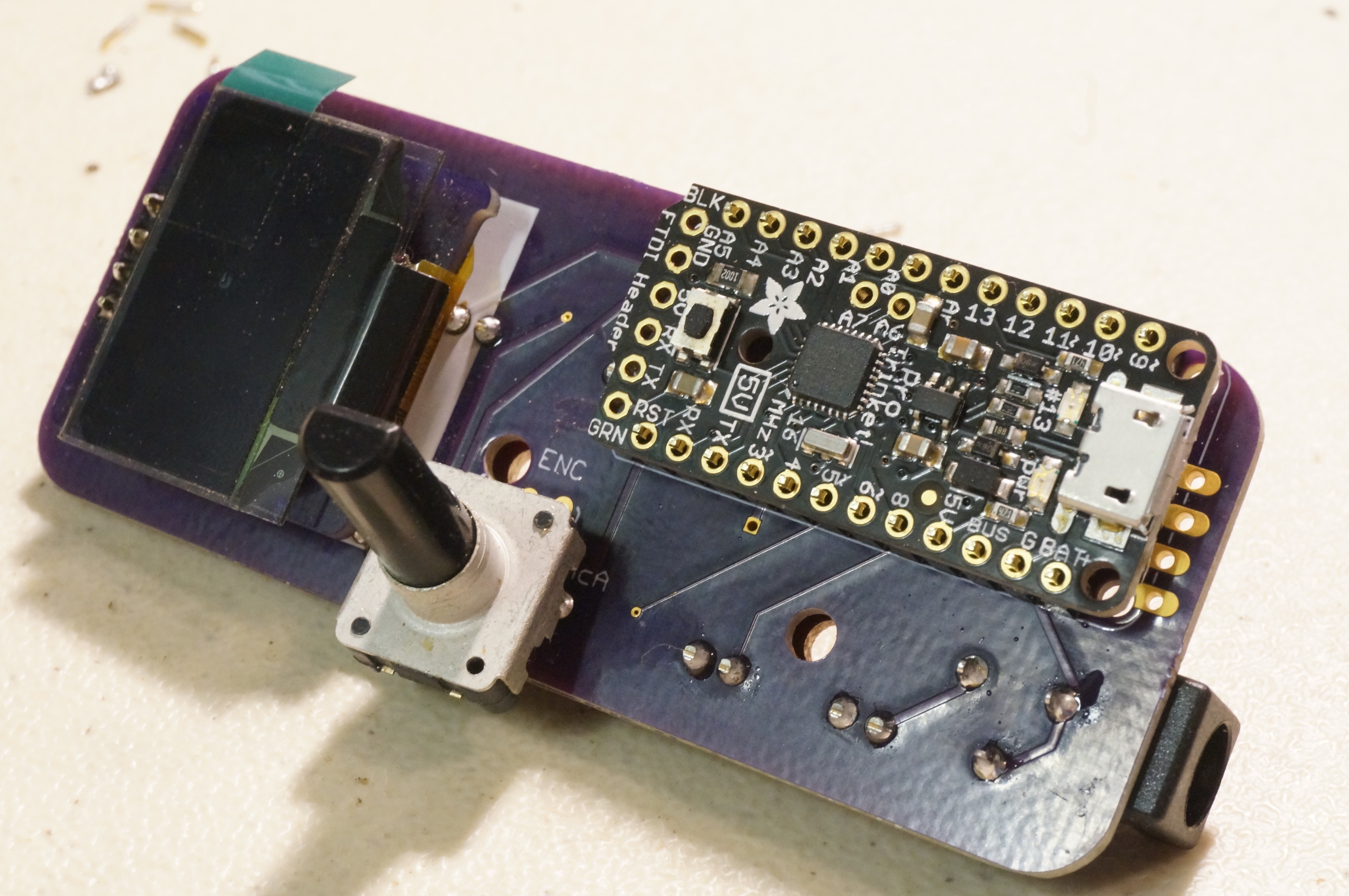
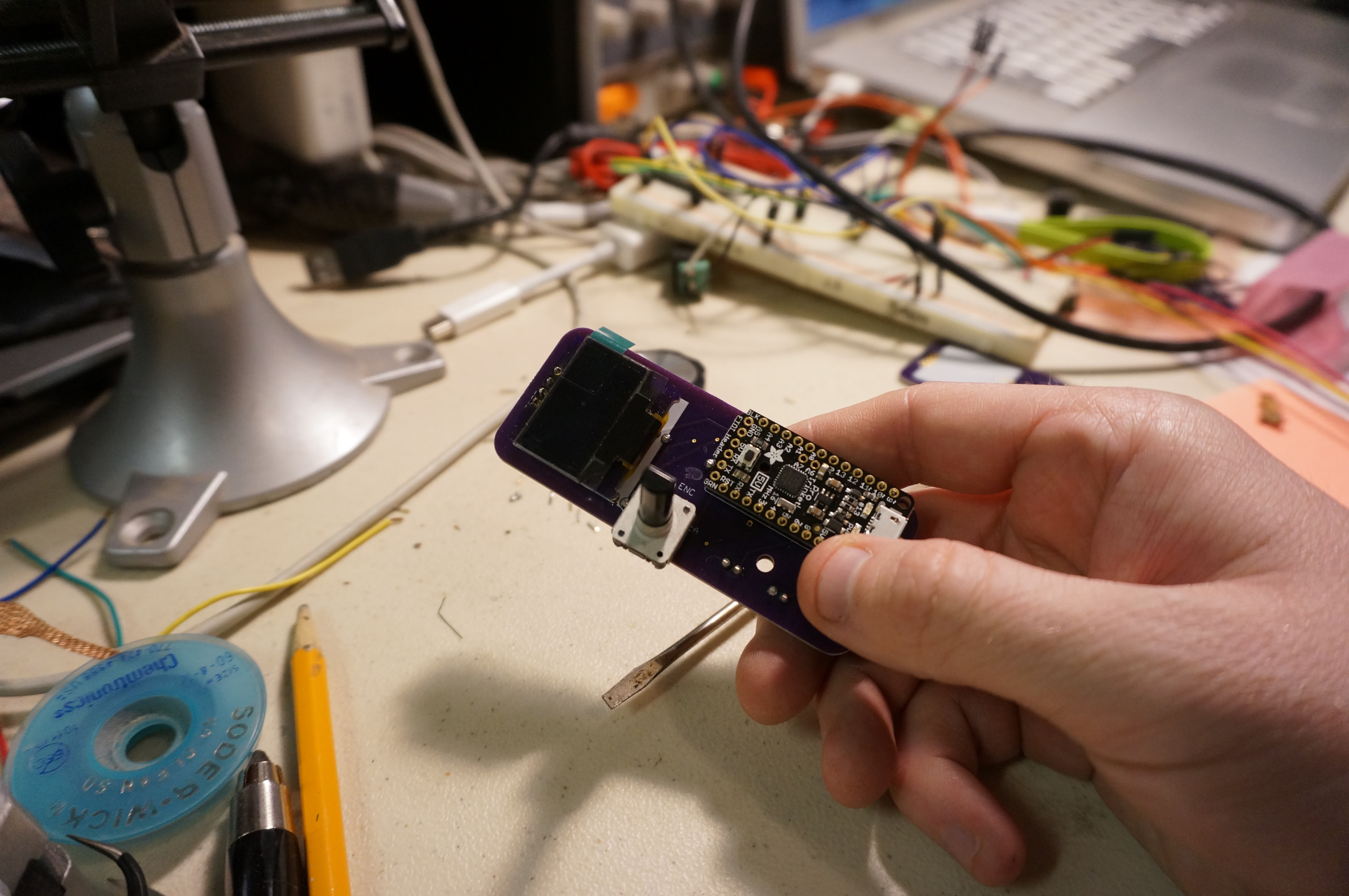
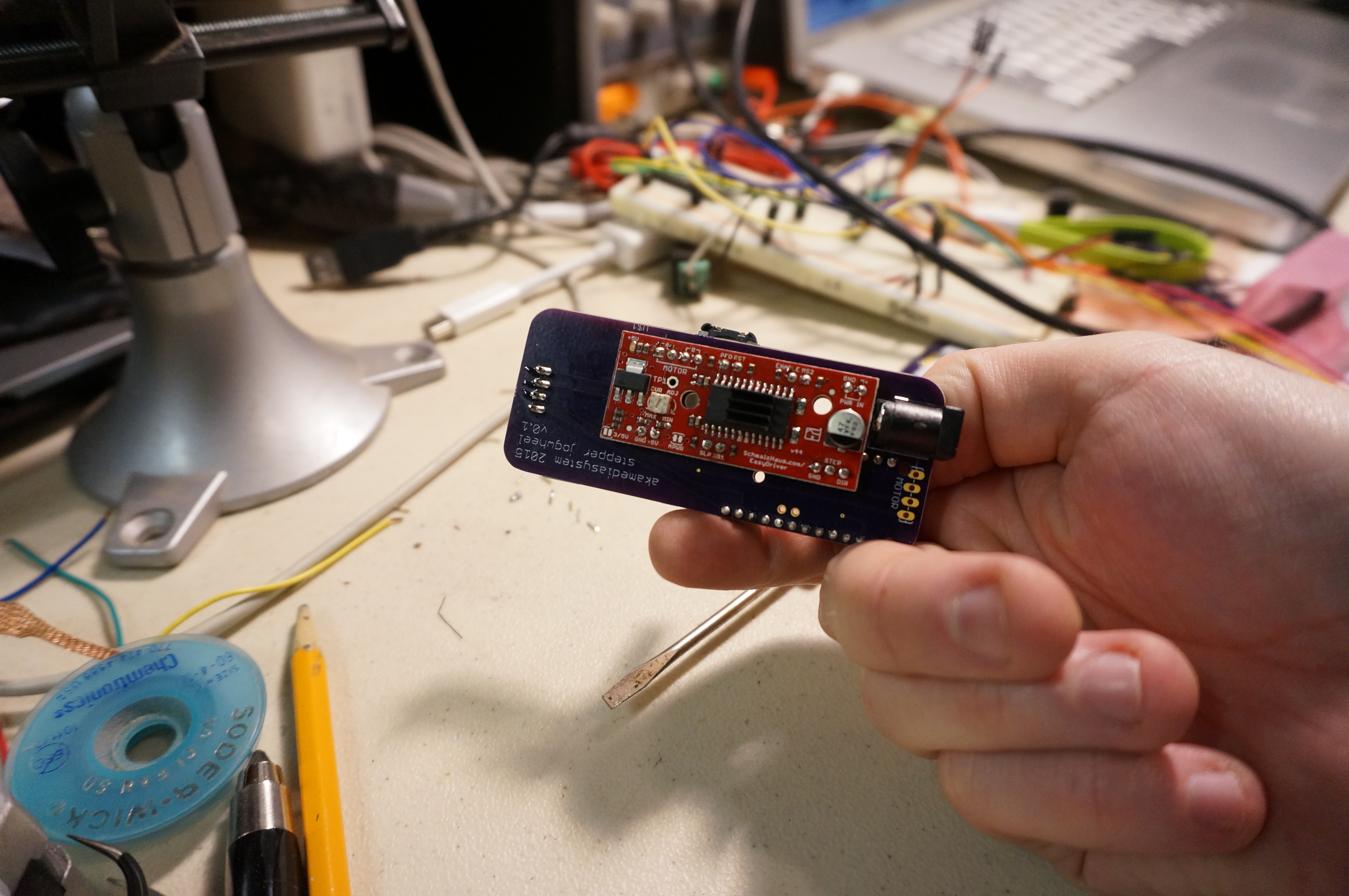
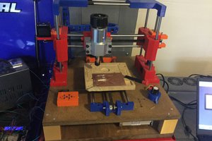
Simple jog dial for stepper motor

This is a simple way to adjust the height on the z-axis of my lasercutter; just a jog dial, readout, and stepper controller

akaAKA
Similar projects worth following
I bought a K40-type cheap lasercutter on Amazon, knowing it would be a lot of work to get running acceptably.

One addition I made is an adjustable-height Z-axis from lightobject.com - this will let me experiment with cutting way more/weirder materials and objects.

I made this jog dial as the simplest, dumbest thing I could quickly get running in order to be able to adjust the z-stage's height without putting my hand in the machine.

The OSH Park boards I had fabbed work well for my purposes, but I will be posting updated boards here soon (even if I don't end up ordering a second batch, purely for cost reasons)

I'm sharing this to save someone else some work. I really don't consider it to be creative, as I just strung together a bunch of different demo code ASAP in order to get something working.

View all 6 components

  • Finishing the project / fixing a noise problem

    AKA09/21/2015 at 01:02 0 comments

    Finally the 4-pole terminal blocks arrived from digikey and I was able to complete the first version of the project. Here's a photo of the installed terminal blocks.

    I found, to my dismay, that there is some pretty untenable noise on the stepper lines - both when powering up and just in general. I threw a large electrolytic capacitor on the barrel jack terminals that appears to have mitigated most of the problems. Here's the cap I installed - this greenwire hack worked fine, but I'll update the board files to accommodate a real decoupling cap soon.

    Three things prevent me from marking this project "done" and recommending that others try it:

    • There's still worrying noise on the stepper lines when the board powers up. Specifically, in the ten seconds that the Pro Trinket's bootloader pauses before initialization. If anyone had any advice about this, I'd be much obliged. (Should I remove the bootloader, which I don't want to do? Should I add pullup or pulldown resistors on the STEP and DIR lines to the EasyDriver?)
    • The EasyDriver gets uncomfortably hot during normal use. I don't think this is out of spec, but I think my design is poor in this regard - it places the back of my hand in close contact with the stepped board. I should design an enclosure to give the user's hand some space away from this!
    • The encoder PCB footprint needs to afford a better mechanical connection to the board. Right now, the encoder is just attached via the three terminals and not the two larger gripper tabs, and I worry I will eventually stress and break the encoder's tabs/

    Improvements aside, I'm happy to be able to move on to getting the rest of the K40 electronics working. Still a long way to go there, though!

  • PCBs back from fab, testing OK

    AKA09/13/2015 at 02:47 0 comments

    The OSH Park boards came today, so I built one of them and did some initial testing.

    I tested the board this morning and all seems to be working properly. I'm still waiting for the motor screw terminals so it's not "done" yet, but all systems are working.

    In the repo, I updated the firmware to make MS1 and MS2 (microstepping settings) addressable by the Trinket. I'll add further firmware updates as they're made, but there probably won't be any large changes.

    I'm thinking of running one more rev of the board to add mounting holes for an enclosure, and a better footprint for the rotary encoder, whose fit is not great at the moment.

  • Eagle boards almost ready to be sent out

    AKA08/31/2015 at 15:22 0 comments

    I spent some of last night laying out the first rev of the board for this project - you can check it out now in the Github repo if you like.

    Even if the board comes back and is functional, I will probably do a second run with more of an eye to the ergonomics - I need to figure out exactly how I'd like to use this, how it should feel in my hand, and whether or not to add extra buttons (ie, toggle the stepper's "enable" pin to allow it to be manually moved, allow inputs for limit switches, and provide an optional header for more common OLED screens)

    I'm not looking to make this a very generic controller - it's pretty specifically a one-channel jog for CNC devices. That said, let me know if I'm missing a crucial feature, it'd be nice ot hear what you think!

View all 3 project logs

  • 1
    Step 1

    The assembly of the board is pretty straightforward, except for one thing: the order of assembly. Getting this wrong will mean a bit of bothersome disassembly, because some components sit on top of others and aren't accessible if they're assembled in the wrong order.

    The correct way to assemble is to solder all the headers to the PCB first. The plastic part of the header should, in each case, be directly under the daughterboard (the OLED, the EasyDriver, and the Pro Trinket). Here is a photo of the headers in place:

    Getting the headers to stay in straight is a bit of a challenge. I used an extra, unpopulated PCB and some alligator clips to hold them straight; you can see the extra board and how I'm holding the piece in this photo:

  • 2
    Step 2

    Once the headers are all soldered in place, test-fit the daughterboards to make sure you have oriented the headers correctly (ie, the plastic part of the header should be directly under each board, making a spacer of sorts).

    Once you are certain of the fit, trim the long ends of each header - the ends that are not sticking out on the side that the daughterboard mounts to. This is important because otherwise nothing will fit. After trimming, you can solder in the boards and the remaining components.

    For the encoder, if you are planning on mounting the whole board in an enclosure, you may want to use a short length of silicone wire for each connection, so you can move the encoder to a more ergonomic position on the case.

    If you're thrifty and feel you may want to reuse the daughterboards later, they are easy to clip off with flushcutters. To make re-use even easier, you could forego the male headers and use female headers everywhere - this would make the assembly much thicker but would allow you to just pop out any daughterboard as desired.

    Here are some final assembly photos:

View all instructions

Enjoy this project?

Share

Discussions

Similar Projects

Does this project spark your interest?

Become a member to follow this project and never miss any updates