 Moritz Walter
The PCBs I ordered from dirtypcbs.com arrived at my door within 7 work days after I uploaded the gerbers. Besides a few drill holes and pads I layouted a little bit too small and the total absence of any connector descriptions on the silkscreen, they're absoluteley spotless and will probably do a fine job.

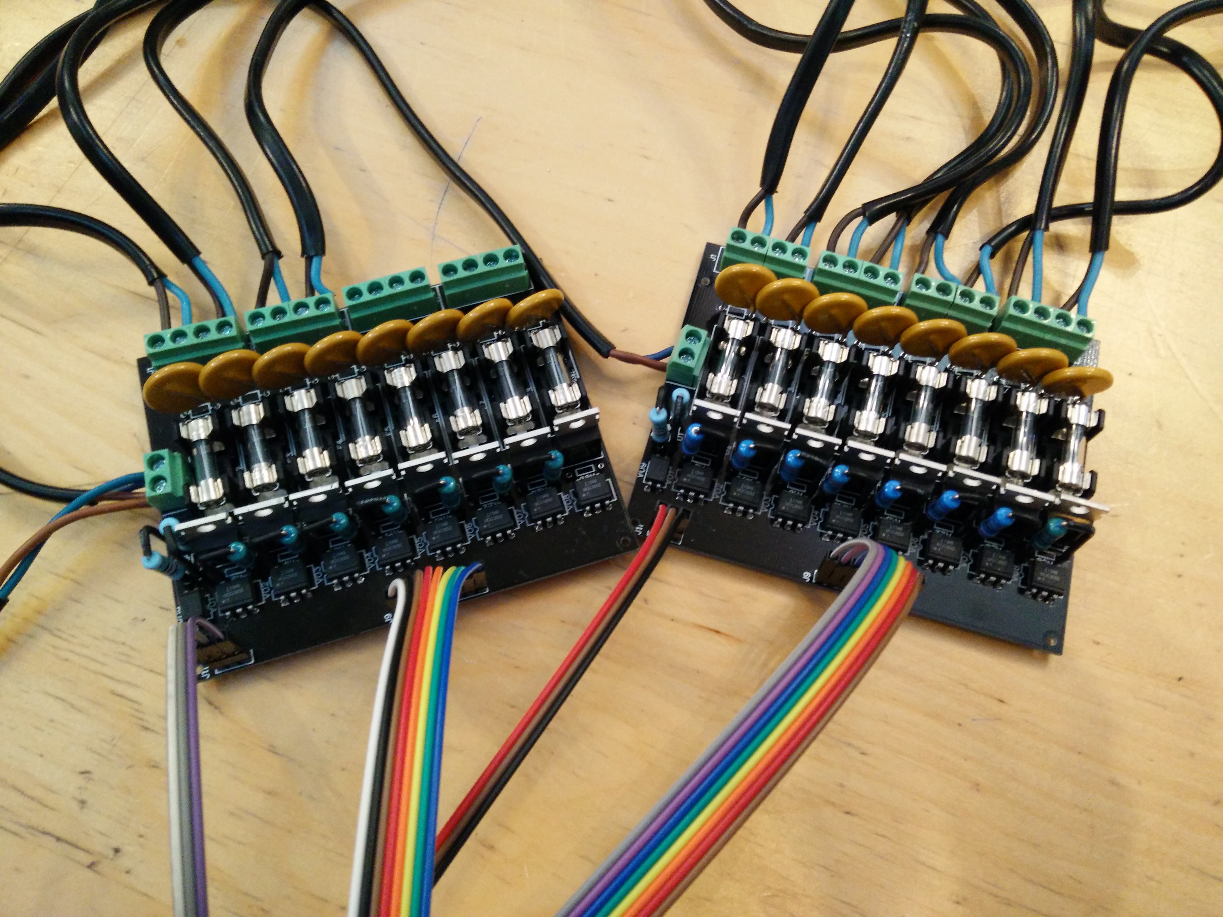
It's solder time. There are some SMDs on the bottom side, but, well, they're shy and have been hand soldered in a hurry, so I better took no photographs of them ;) The top side is where all the fun happens, optotriacs, triacs, fuses, 1W resistors, varistors, everything squeezed to the minimum possible space which is given by the TO-220 triacs and the fuses. I really wanted to use dirtypcbs, so I had to stick with 10x10cm maximum board outline.
If you want your PCBs to be compatible to 5mm AND 5,5mm terminals, you can just space them 5,5mm and make the holes a little larger. Then, you just group them in 2x2 blocks and they fit nicely. We don't really care about terminal distances, so we want to use what we can source the cheapest at a given time, right?
I've put together a little Teensyduino-Demo for testing the boards. They already have the cosinus and gamma correction, which is very visible I find. If I have time I'll take the extra mile and demonstrate the difference. There are only 12 bulbs attached in the demo, which were all I had, so there's a gap in the animation.
Eventually, I'm kind of happy with the boards as they are. The resistors in the zero crossing detection circuit get a bit hot, but they probably won't fail. I didn't get shocked (neither did anybody else in the Attraktor makerspace), nothing caught fire, so that's already great. And even more than that: the damn thing works :)
Discussions
Become a Hackaday.io Member
Create an account to leave a comment. Already have an account? Log In.