 Glenn
GlennI vacuumed Zurg off and proceeded inspect the base first. Underneath we find
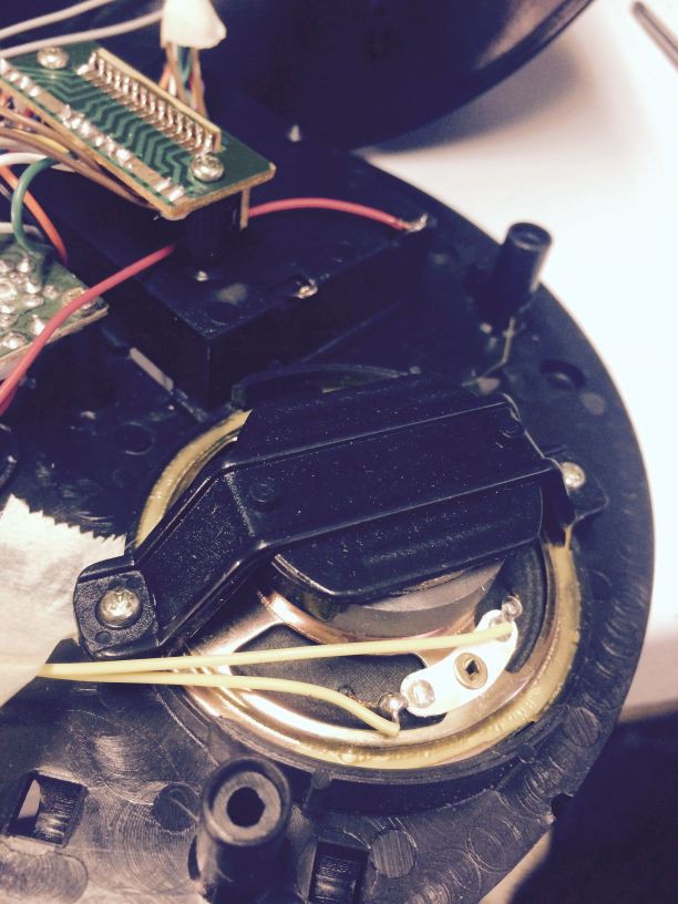
- Speaker
- Battery holder for 3 Double AA batteries
- Base switch to activate Zurg manually
- A play or try me switch. Base switch is currently working with this switch in either position. (Note: So I ended up looking up the instructions for Zurg and found out that you have to arm him in order to have him monitor the sector).
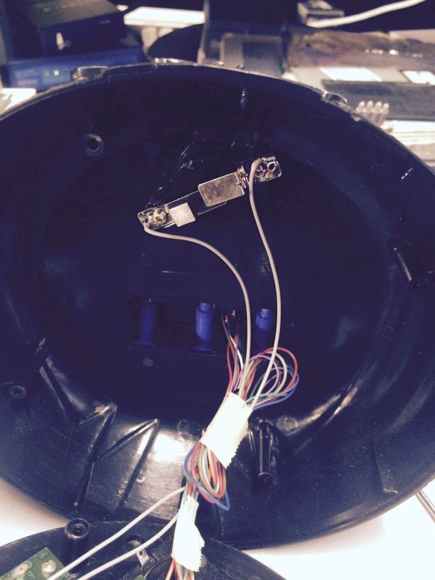
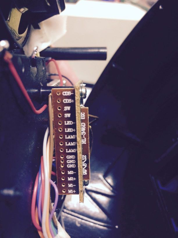
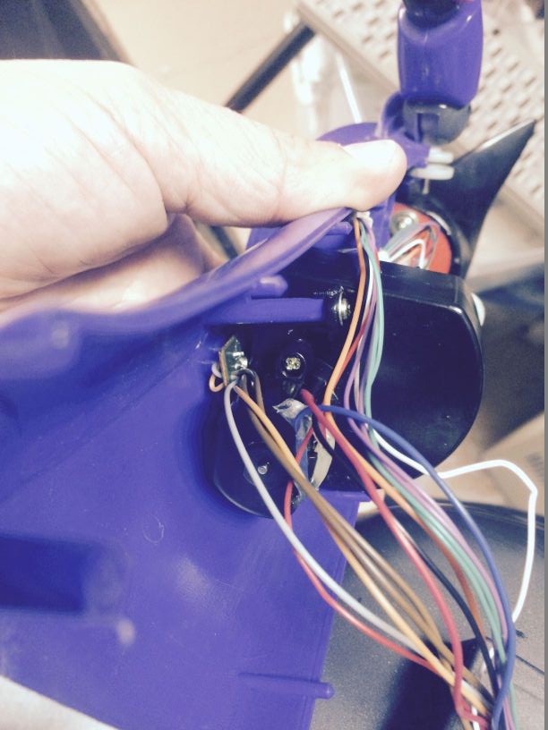
- Wire bridge PCB that handles the transition from the main PCB to the sensor, lights and motors in the main body. I expect it there to provide some possible strain relief and or just make assembly easier. See photo for connections.
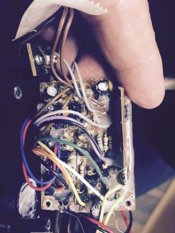
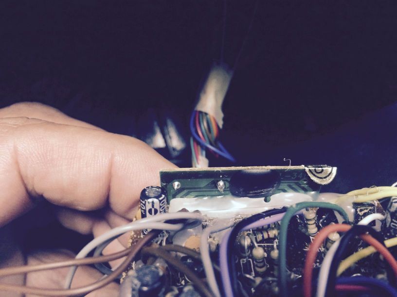
- Main PCB is comprised of two parts. One smaller daughter board which just has a resister and one black blob, and the main board which has resistors, caps and transistors. All caps look to be okay (no swelling)
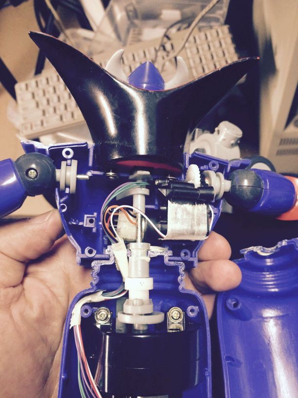
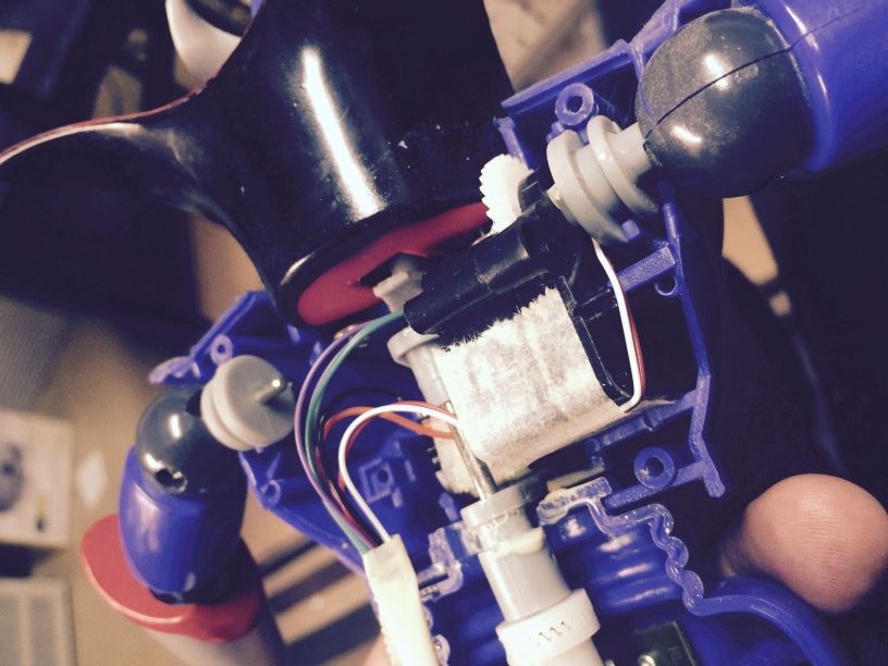
Next I took apart his body (reluctantly to determine which wires were for the sensor) and found
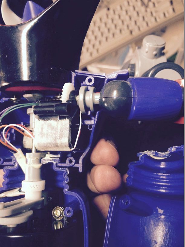
- Main body motor which turns his upper body and his head.
- Arm motor
- Mouth light
- Eye lights
- Gun light
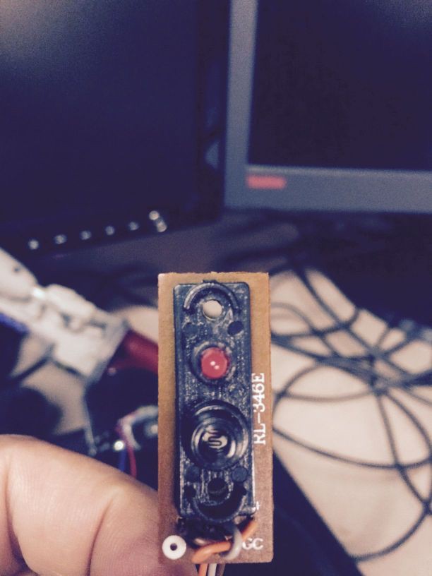
- Sensor led
- Movement sensor (Looks to be a Photo Resistor). PCB marked RL-346E
I plan to use upverter to document the system and the circuit. Seems to be lots of room in the base to put an esp8266.
So for my project I will want to remote activate the Zurgotronic Patrol System (simulate base button press - twice quickly). Pass the sensor and led circuit via the esp8266 so i can control when the led lights or the Photo resistor is enabled. Optionally control how zrurg moves side to side by controlling his body motor. Add support for a camera to capture the intruder?
Most of these photos are self explanatory but I'll add captions for completeness
Base
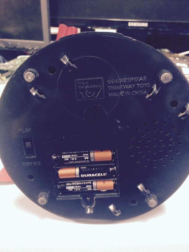
Base switch
Speaker
Main PCB - Bottom View
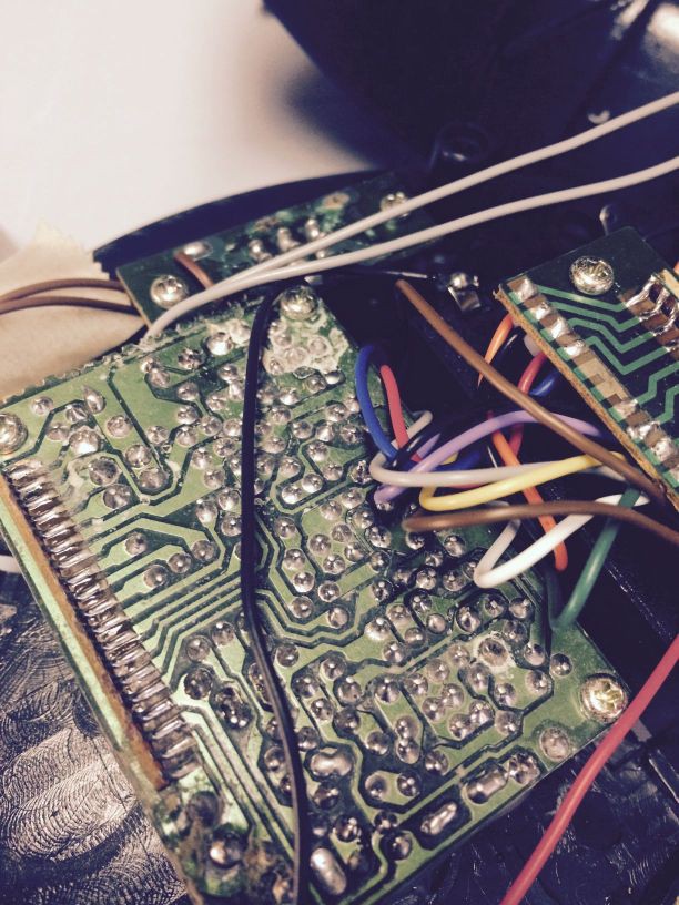
Main PCB - Top View
Lots o hot glue
Main PCB - Blob View
- I am guessing it is some kind of MP3 player chip
Wire bridge PCB
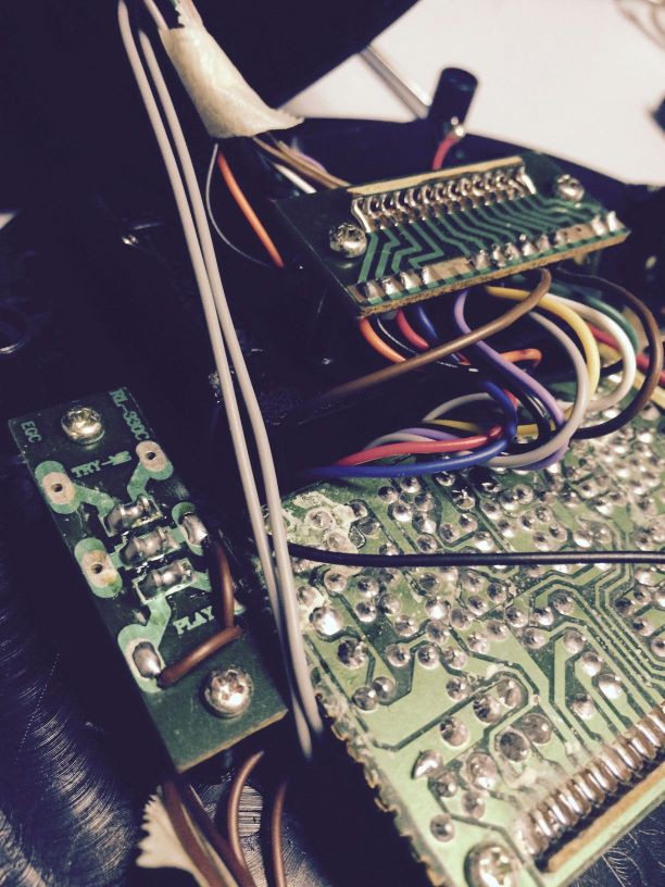
Wire bridge PCB - close up
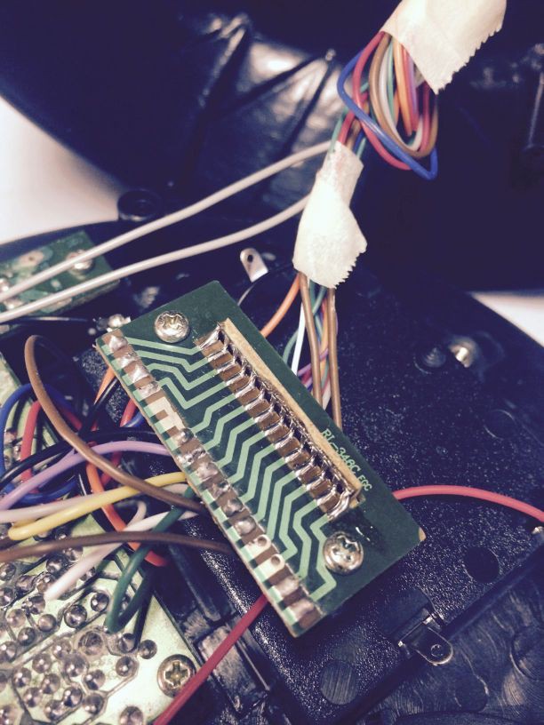
Wire bridge PCB - pinouts
Main body and arm motors
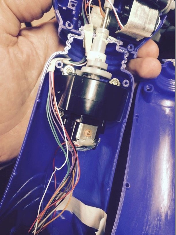
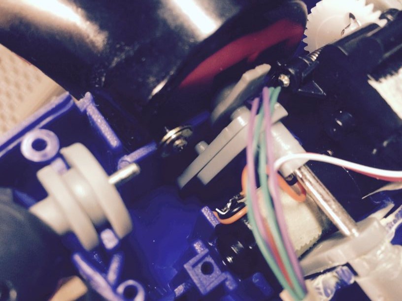
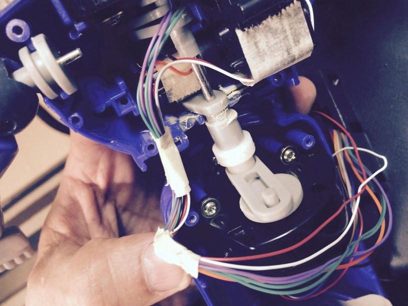
Wiring
Zone Activation LED and Light Sensor
Discussions
Become a Hackaday.io Member
Create an account to leave a comment. Already have an account? Log In.