 Eric Hertz
Update (9-10-15): Adding a photo of my circuit (at the end of this log)
--------------
One potential option is using the DVD-laser for etching, etc...
Doing so requires a driver...
Apparently the de-facto laser-[diode]-driver these days is called the "DDL" and is shown below:

This circuit is *everywhere* online, in various forms, but allegedly was first-introduced to "the laser scene" by a dude going by "Daedal." I believe this is the first introduction: http://laserpointerforums.com/f42/diy-homemade-laser-diode-driver-26339.html
Actually, I had to search quite hard to find this *source*, as there are *many* others out there that reproduce it, and apparently few know exactly how it works, including, apparently, Daedal, himself, judging by quotes I've read in those "many other" sources.
Granted, I haven't read-through the entirety of the 92 pages of forum messages at that link, nor even bothered to read Daedal's explanation, as I'd gotten quite tired of reading the same thing from source after source, before finally finding *the* source... maybe the answer is in there. But I have *searched* that forum for some answers and they all seem completely unknowledgeable (some flat-out wrong) on some specifics, including quotes from Daedal...
So here's my interpretation of this circuit...
The basic gist is to supply the laser-diode with a constant current (not voltage).
The reason...? I've read (though don't remember where) that laser diodes, unlike regular LEDs, have a tendancy for their forward-voltage to change as they heat up, such that if driven with just a resistor (like an LED), they will actually burn themselves out. So that must mean that as they heat up their forward voltage drops, which causes more current to flow through them, which causes them to heat up more, until they eventually overload.
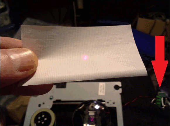
Again, I can't remember where I read this, but it seems that a "burnt out" laser-diode essentially acts like an LED... it won't "lase" and it won't be very bright. You'll pump a huge amount of current into it and basically get a very very poor LED. I have seen this happen. 250mA is barely bright enough to see through a sheet of paper in a poorly-lit room at night.
THAT SAID: It's still not wise to allow that light to hit your eyes directly, and probably not even indirectly. AND CERTAINLY not a *functional* laser's light... so be careful. Seriously, if it hurts to look at its reflection off a wall, then turn the power down and get goggles. And if it doesn't hurt to look at its reflection, then either it's not functioning, or you're well-suited for the Darwin Award.
Where was I?
Oh yeah, so the basic idea is to drive the laser-diode with a constant *current* rather than a constant voltage with a current-limiting resistor (as one would normally drive an LED). Then, with a constant-current-source, it won't matter if the forward-voltage of the laser-diode changes.
Now, I'm not certain this is *ideal* but it certainly works well enough that most people hacking old laser-diodes seem to use it.
So, there's an LM317(T) VOLTAGE-regulator USED AS a current-regulator. There is, in fact, an example of this in the LM317 data-sheet, so I won't go into its details. Suffice to say, in the configuration shown in the schematic, it will attempt to supply a constant *current* to the load (the laser-diode, in this case).
Now, there're a few places where Daedal has been [plausibly-mis]quoted regarding this circuit's functionality... For instance, I can't seem to find *any* reliable explanation of why the 1N400x diode exists. Yet, everyone seems to repeat it in their own circuits, with zero explanation... some have even replaced it with Schottky diodes.
The best explanation I've found is that it's in case the battery is wired backwards. That's great; it will protect the Laser-Diode (which are hard enough to come by), but most-likely will fry the rest of the circuit. Better that, I suppose, than attaching a diode straight across a Li-Ion battery, where it might result in fire... but really not at all reliable in any case. The alleged second reason is because it causes a .7V drop when the circuit is properly-wired, which... I dunno, frankly it's absurd... If the circuit is wired correctly it seems obvious to me that the diode will be OFF. THAT SAID. There are other potential reasons... one suggested by my buddy @Les Hall...
Somewhere I vaguely remember having read that laser-diodes may have *really low* reverse-breakdown voltages... so, imagine an LED which turns on when the voltage across it is +1.7V... generally you can assume that reversing that will be safe... e.g. -1.7V will result in the LED being OFF AND not conducting any current. Or, imagine a 3.6V Zener Diode... Its forward-voltage is ~0.6V, but its reverse-voltage is the zener voltage of 3.6V... A zener-diode is designed to handle that, but a laser diode is not. So, as I probably mis-understand it, there's the plausibility that a laser-diode might be FORWARD-BIASED at say 1.7V, like an LED, and power-up... but that if it's REVERSE-BIASED, even something like 1V might fry it. Kinda defeats the "diode" qualification, but I could be entirely mistaken about this entire thing.
Regardless, in that case, putting the 1N400x diode *reverse-biased* and in parallel with the laser-diode should protect the laser-diode from reverse-polarity.
Now, there're other characteristics of the LM317 that aren't explained in the datasheet for the current-supply schematic that *are* explained for the *voltage-regulator* schematic... e.g. where to place protection-diodes. Most of these are placed to protect the LM317, rather'n the load. The logic might be extendable, but my brain isn't working in that realm at the moment (feel free to throw your two cents in the comments!) As far as I can tell, this diode, in this schematic, serves no purpose other than plausibly what my buddy Les suggested... That maybe it's there to protect the diode from *inductive* properties of, e.g., really long wires going to the Laser-Diode from the current-source. Plausible, actually.
Now, I just burnt my second laser-diode, it seems... (the first seems fine). I built the same circuit, but not identically to my first. The first included that diode. It ALSO included placing the *capacitor* *at* the laser-diode, rather than in the current-source circuit.
Again, somewhere, I read that it's a wise choice to make sure that capacitor is discharged before connecting it to the laser-diode. Hmmm... that actually makes a heck of a lot of sense...
The "proper" method for going about this whole thing means making sure your current-source circuitry functions as expected *before* plugging in your (valuable) laser-diode. It's smart, there're several explanations out there about how to do it. But there seems to be one key factor missing in those explanations... and that is: If you power up the circuit *with no load* then that capacitor will be charged to your *source* voltage. Then, if you try to wire in the laser-diode, even after removing the power, it will likely be zapped by the source-voltage stored in the capacitor.
In this second laser-diode attempt, I have *both* long (potentially inductive) leads *and* the capacitor is wired at the circuit, rather than directly across the laser-diode... Further, I didn't include that diode because it seems completely absurd. Plausibly each are bad, on their own, and combined... who knows...
That said. There *is* a means to do this test-procedure properly such that there's no risk to the laser-diode, but my brain's not there, right now. I'd Suggest: Wire up that reverse-diode AND that capacitor directly to the laser-diode... keep that as a singular "laser diode" unit... Then perform the current-output tests suggested elsewhere. Then, when you know the current output is correct, then make sure whatever capacitors are in the circuit are completely discharged, and only then add your laser-diode "unit".
A further Step: The circuit above shows a 4-ohm resistor in series with a 100ohm potentiometer.
A) I'm not doing the math right now, but elsewhere it's suggested to use a 5-ohm resistor (or a parallel of two 10-ohm resistors) in series with a 100ohm pot. That (5ohms) results in a maximum output current of 250mA, when the potentiometer is at 0ohms. Seriously, if you value your laser-diode (or your eyes): Start with the pot at its maximum resistance (100ohms) and decrease it *very* slowly to increase the output current and the laser-diode's brightness. 250mA is the maximum recommended (on notoriously questionable sites) for a 16x DVD-burner laser... so, it wouldn't be wise to use a smaller resistor than 5ohms until you're absolutely certain you're willing to risk burning out your laser-diode. (Yes, you *could* neglect the 5ohm resistor altogether and rely on the potentiometer alone, but do you really want to risk adjusting that pot to 0ohms and running 1.5A through a laser-diode rated for 250mA?).
Now... where does this leave us...?
Connect that capacitor--whose value is allegedly just whatever the original circuit-designer happened to find on his desk--and that reversed-diode right to your laser-diode. Consider that entire thing a singular unit from now on.
Try not to use overly-long leads between your current-source circuit and your laser-diode... My functional circuit has about 6inches, so who knows what "overly-long" really means, but I wouldn't, say, run a 15-foot wire between the laser-diode and its current-source circuit...
Now, what else... Oh, the LM317 has a minimum voltage that it must maintain between its input and output, something like 3V... So, if your laser-diode's rated for something like 1.7V, you need to supply at least 1.7+3V+1.25V to the circuit. (The LM317 tries to maintain 1.25V between the "adjust" pin and its output pin, the adjust pin is wired to your laser-diode). The LM317 acts as a varying RESISTOR, in order to maintain the proper output-current... this means it will HEAT UP. And the higher your input voltage the more heat it will produce. I tried mine with a 12V wall-wart, which was actually outputting something like 16V... it got quite hot to touch, but probably not too hot to function. A heatsink on the LM317 isn't a bad idea, though.
What else...? That's all I can think of, for now...
SERIOUSLY: If you don't wish to win the Darwin Award: BE VERY CAREFUL with lasers. "Do not look into the laser with remaining eye." But, even beyond that, the power-output by these lasers is high enough to be painful just reflecting off a wall... Pain is there for a reason, to protect you. Don't try to be all manly and fight through it. Use goggles, the proper ones rated for your laser's wavelength. And, be careful what you buy online, just cause it *says* it's for your wavelength doesn't necessarily mean it is. (seriously, slightly-yellow-tinted goggles are going to block highly intense red light? I dunno, seems questionable to me). Oh yeah, and if you're working with IR-lasers... you won't see the lasing in your eyeballs, but if you're lucky you might see the sparks of flames burning your retina before the whole thing catches fire... Don't win a Darwin Award. The End.
Here is a photo of the circuit, as I've implemented it. Thank you to @frankstripod for locating it in the animated-gifs of the later "Laser Focussing Experiments" post!
Discussions
Become a Hackaday.io Member
Create an account to leave a comment. Already have an account? Log In.