 Eric Hertz
Here's the first-go at a rotary-tool "chuck"... I described it quite a bit in yesterday's log. The end-result was, my tools just aren't precise enough to make this work. There's way too much "wobble", and unfortunately a bearing on the second shaft just doesn't seem to help.
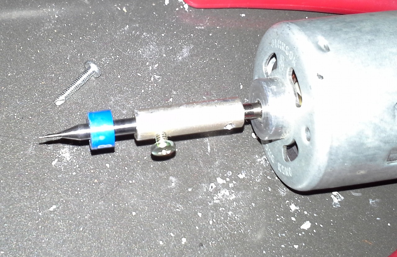
It's mostly due to not having the right drill-bit size, which required widening by-hand, which is just not very precise. The bit's shaft is actually not at all coaxial with the motor's. No amount of bending the coupler would align 'em... If the bit's parallel to the motor-shaft, then it's offset.
(Also, the bolt in the picture was a nice find, a self-tapping bolt! I used it to tap the set-screw holes, worked great!).
I tried a second-go with similar results. Maybe I'll try again, and plan to have a bearing at the bit, but that's on the back-burner, due to drill-bits.
Here's the new design:
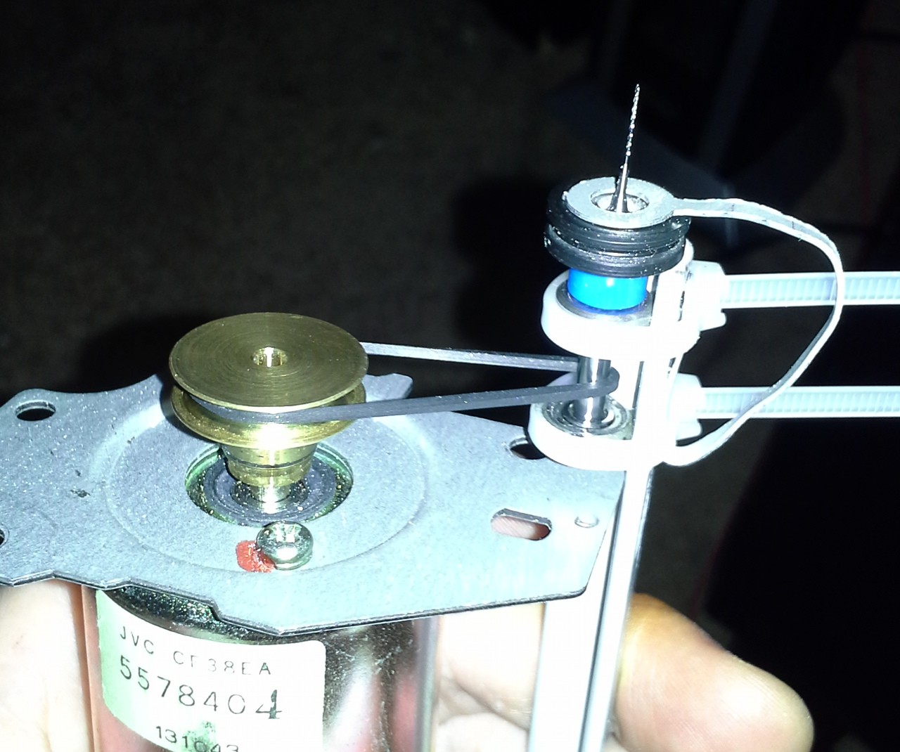
This new motor is *much* quieter, plausibly at the cost of speed. But it's also geared-up... Did some test-drills with a PCB and it seemed to *drill* fine, routing is another issue.
Two bearings are zip-tied (for now) to angle-stock, at either end of the bit's shaft. The third bearing (these bearings are actually from pulleys, I left the pulley on the third bearing). The third bearing prevents the bit from riding up and down. This is a quick-test, thus the zip-ties and cheesy support for the third bearing.
There's a new problem, now... These bits are *tiny,* just small enough for spaces between TQFP pins (nice!). BUT, they're *drill* bits, meant for plunging, not for side-cutting. I've broken four or so of these today, alone.
So, one consideration is possibly doing several *really shallow* passes, and I built a test-rig to try this out (see below).
Also, heat... I dunno why it didn't occur to me, but it came to light with the test-rig... those bits can get hot! I'm not sure whether the heat I felt would be matched with *really shallow* passes, but if it's close, I'll have to worry about whether the rubber-belt will hold up to it. That's another consideration for later.
Here's the test-rig:
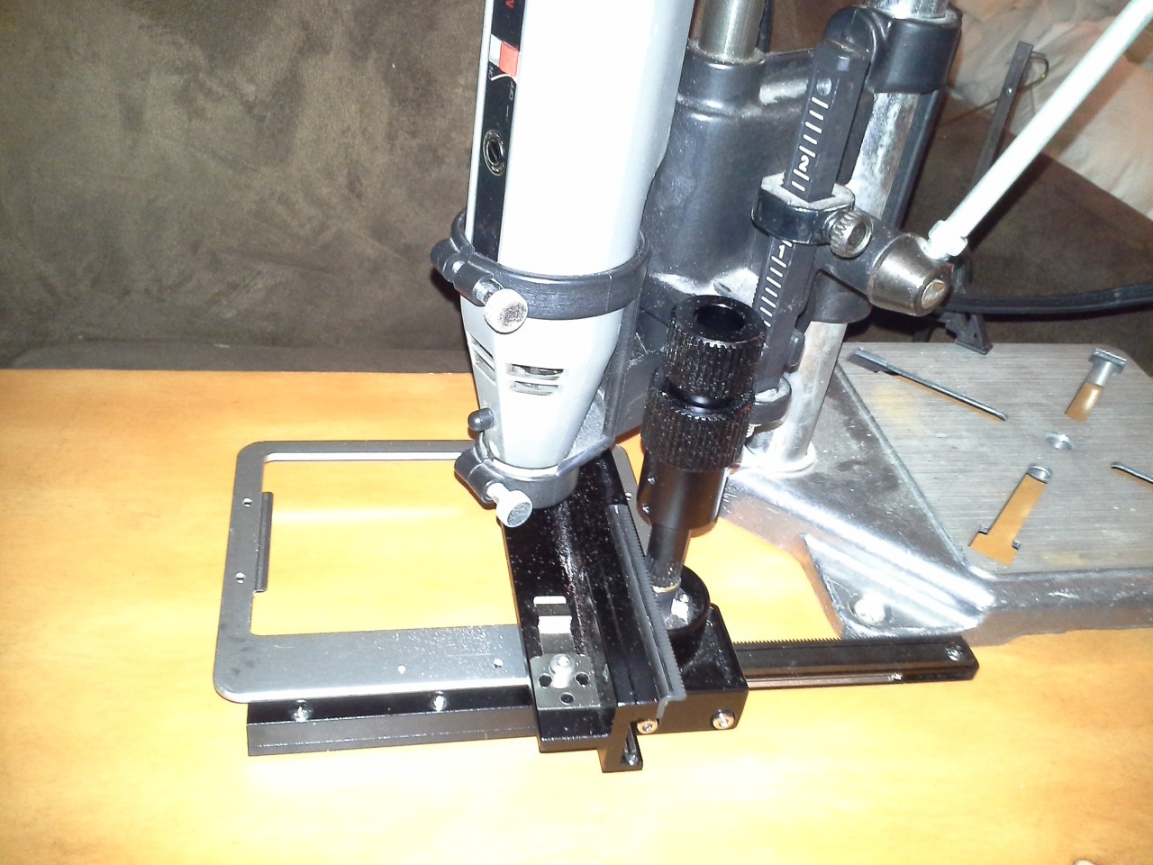
I mounted the PCB on the really sturdy axis right under the rotary-tool (this is the axis that might eventually support the tool) and did several passes in a straight line.
Not the best test-rig, by any means, but certainly better than trying to hold the tool in one hand and the PCB in the other. The drill-press stand doesn't have particularly high-precision on the vertical motion, so I managed to apply too much pressure at times, and other passes where it wasn't cutting at all. (Thus, maybe, the heating of the bit might've been due to too much pressure).
Here's the PCB (it was an early experiment with toner-transferring, several several several years ago):
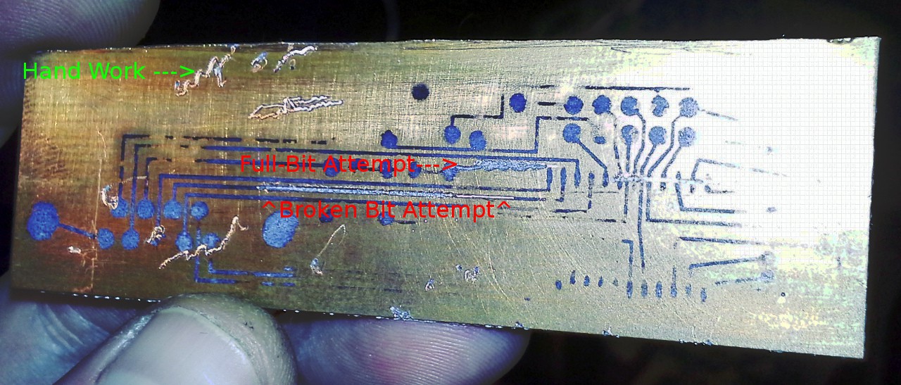
The cut-squiggles are the results of trying these experiments by hand... Hard to do, the bit spins, and tries to walk. So with the test-jig I did several straight-lines, the best one's right in the middle. There's another experiment, kinda hard to see in the image, but above and to the right... That's the first test, with a fresh bit. The fluted part of the bit is quite long (half an inch?) and even with the test-jig the end of the bit managed to "walk" in a sinusoidal pattern that varied whether it was moving left or right. Possibly, with higher vertical precision and smaller passes it might work... But I managed to break the bit before another attempt.
So, the straight-line was done with a broken bit, only about 1mm of flutes remaining. I didn't have high-hopes for this working at all. With my hand-attempts, the broken bits seemed to have no cutting-power, they just marred the surface, and I couldn't even get them to plunge 1mm. But, three passes with the test-jig, and I broke through the copper and managed a pretty clean cut, as well. This is actually quite promising.
I think the width of the cut is larger than the bit, however. There could be several reasons. Of course, a broken-bit isn't really meant for cutting, so there's probably some weird forces at play. They might be causing some play in the rotary-tool and/or its mount. Regardless, I might not be able to do TQFPs with this setup, but obviously larger-pitch surface-mount would be doable. Besides, my understanding is that TQFP is difficult without a solder-mask... (That won't prevent me from trying!)
So, actually, this broken-bit multi-pass technique might be just-right. I did some searching for routing-bits and the smallest I found was 1/32nd (for $20!) which ain't too small when thinking about PCBs. And, hey, I saved all my broken bits :)
I'm not sure about the new design, using a rubber-belt... There's the heat issue, and there's the difficulty in actually replacing the bit. It's doable, but definitely not quick-change. And, it only works with bits that have the plastic sleeve. And a few other factors. OTOH, as nice as the other motor's knurled-shaft was for press-fits, it is *really* loud. Some thinking to do.
And, I mentioned yesterday that I had been filing-down the shaft on a right-angle drill-attachment. The purpose was to use it with my normal drills for its bigger chuck. Now I can use drill-bits with shafts up to 1/2in in diameter! Nice. But then it occurred to me that I could use it as a lathe...
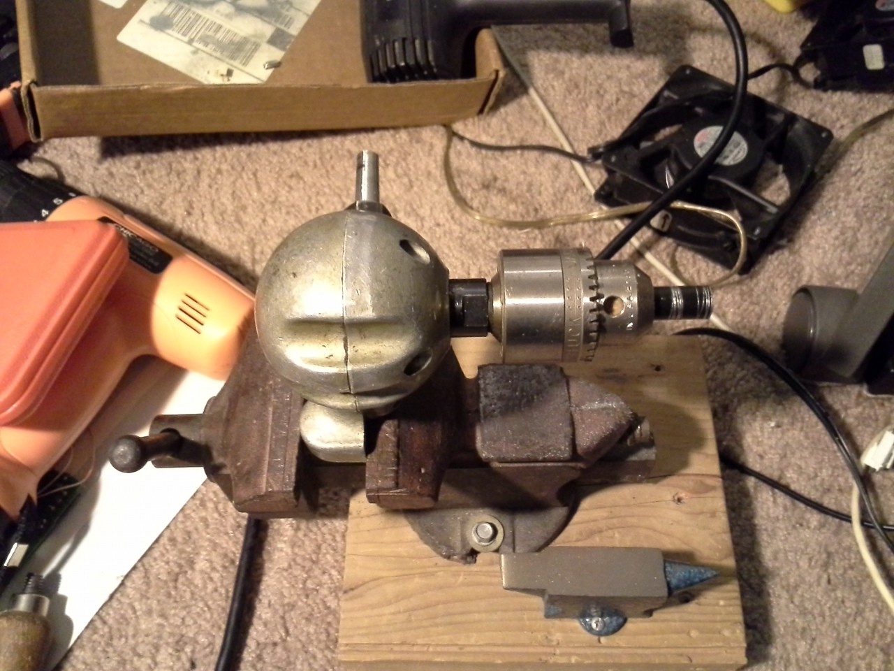
In the chuck, in the image, is the 1/2in "pipe" I originally tried to use for mounting my bearings. I used a hack-saw while it was spinning, to cut straight-through (hey, no wonky-hack-saw angles!).
The shaft (sticking "up" from it, in the picture) took *hours* to file-down to fit in my drill chuck. Fun!
Discussions
Become a Hackaday.io Member
Create an account to leave a comment. Already have an account? Log In.
I'm using these bits: http://www.ebay.de/itm/190871687465?ssPageName=STRK:MESINDXX:IT&_trksid=p3984.m1436.l2649 ...with questionable success guiding them by hand. At that price I'm not too worried about breaking them though. If you want I could send you a few [I do ship to Brokeasheck :) ]
How come the holes for the motor shaft and the bit weren't coaxial in your first chuck? I'd assume you first drilled through the entire chuck/coupling and then widened the ends to fit the motor shaft and bit respectively. Regarding not hitting the exact center of the cylinder, you might be able make up for that with your new 'lathe'.
edit: Nevermind, I got around to reading the previous log.
Are you sure? yes | no
Ah hah! Those do look precise! And, maybe, even hackable ;)
Brokeasheck is a LONG way away from your home-town, shipping would cost more than the parts! But I do really appreciate the offer!
I see you beat me to the explanation, but yeah the short of it is the
first-run was two drillings, one from each end (dumb!). Plausibly combined with some warping due to the press-fit. And the second
was the result of differing shaft-sizes and the lack of a well-sized bit
for one of 'em, resulting in hand-widening by wobbling the drill-bit around in the hole.
Definitely the new "lathe" is in consideration for later attempts. Might have to make some additional tooling for it :) Since the rubber-belt/heat issue became a concern (again, late in the game), I'm rethinking how to do a shaft-coupling. That link you sent (was it MIT?) gave me some ideas... E.G. maybe use a larger premade shaft-coupler (which I might have) and some spacers. Or maybe I'll dig out a motor with a really huge shaft and drill out its center... hmm... Not sure how much my Z-axis would like that... but I'm definitely not ruling out home-made head-on-coupling as a possibility.
Or maybe some combination; another 1/8th inch shaft with sturdy-bearings at either end, and a shaft-coupler to the bit, and a pulley/belt between, more like a mill. I can drill a pretty good 1/8inch hole with my tools :)
Are you sure? yes | no
Shipping would cost more but Deutsche Post is actually quite affordable.
The bits' precision means nothing if the spindle/chuck isn't. I checked out #PCB mill for under $10 again and if the bearing for stabilization doesn't work out I'll just try @shlonkin's approach.
Even if you drilled out the threads from two sides it should still be coaxial I think. So yeah, maybe it was another factor that lead to the holes not being coaxial anymore but modifying a standoff sounds promising.
Drilling out the motor shaft, again, has the problem that you have to hit its center which I probably couldn't do on the first try. Using pulleys has the advantage that you can modify their ratio and speed up the spindle with respect to the motor rpm which might also be useful. I feel like those bits would profit from something like that.
Are you sure? yes | no
@Stefan Lochbrunner Good reminder about that project... Just shows-to-go-yah what can be accomplished with hotglue, threaded-rod, and cutting-board ;)
The motor I have in mind actually has an indent in the center of the motor-shaft... but it's *HUGE* so I doubt I'll be using it.
Are you sure? yes | no