 Eric Hertz
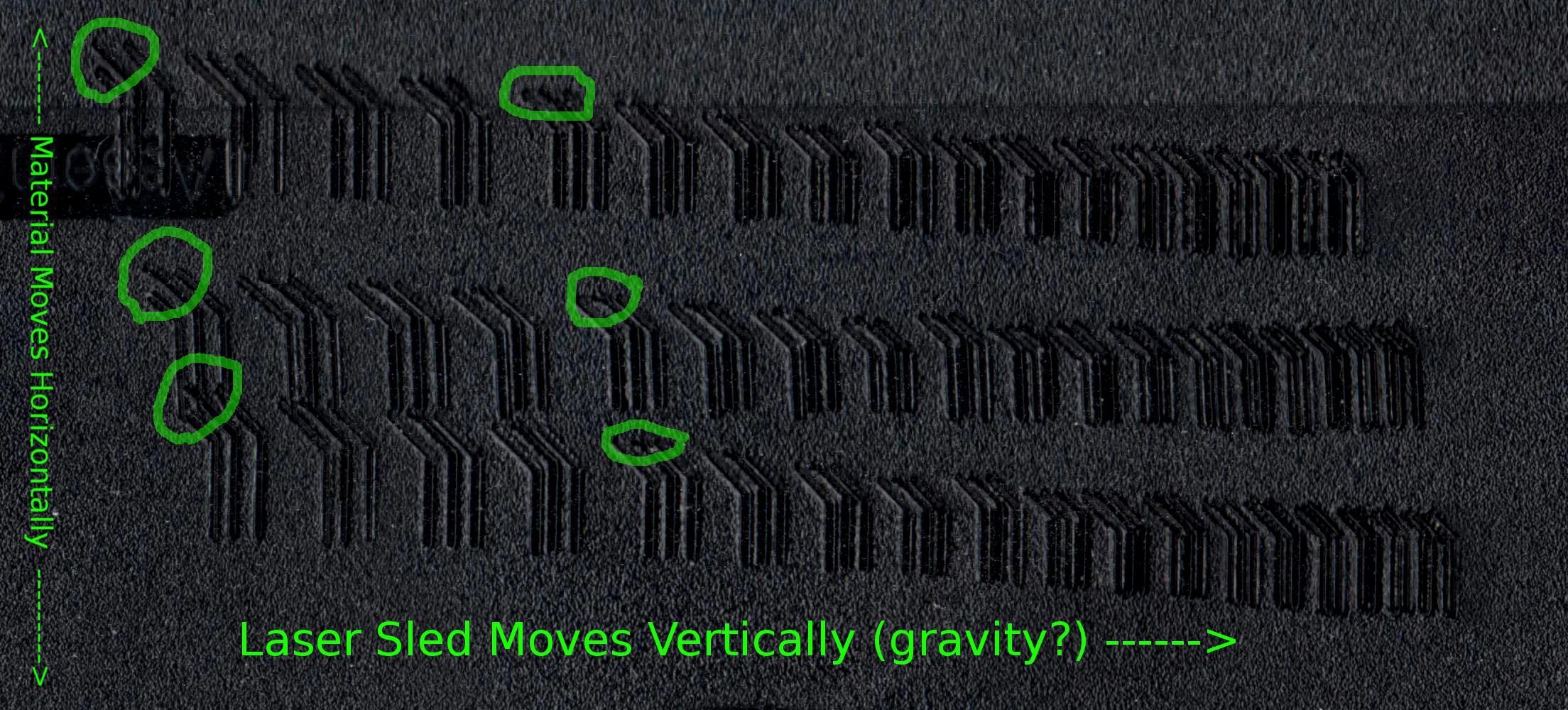
The bottom two test-runs are identical settings, just testing repeatability. The upper test-run was after bumping my motor-driver's voltage from 5V to 12V (those motors were HOT).
Click to zoom that biznitch and look at the circled portions. Note that the upper portions of the diagonals are often sloped shallower than 45deg. Why? And note that it's less-apparent (if not non-existant?) when powered with 12V. So, I'm thinking that maybe the laser-sled, since it moves vertically, might be having some gravity-effects which are less-apparent when the motor's got a bit of momentum and also when it's got more power...
Consistency-wise, it seems all three test-runs show nearly identical characteristic oddities in most other cases...
E.G. the uneven spacing of each triad... why aren't those center "traces" centered? And why is it consistent on *all* test-runs...? Am guessing that these are full-steps and the microstepping configuration just isn't strong enough to hold the sled between two steps (but it's OK when moving...?) And, then, wouldn't they have little "tails" from the microstepped position it would've started at when moved to the starting-position, then a straight-line where it settled...? Not seeing that on the perpendicular traces, but it's kinda what I'm imagining to be responsible for the shallow-diagonal-"tails".
Note also that this test-run (melting into an old floppy-disk) is much more consistent than the original cardboard-test-run...
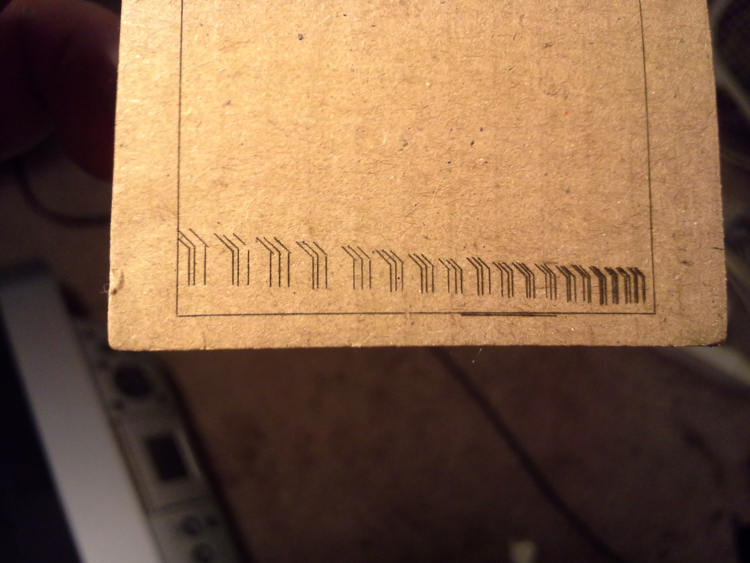
I've since done several more cardboard-test-runs, and have gotten pretty flakey results. I think it's *just* past the threshold of actually burning the material, so any differences in the fiber-density, (maybe skin-oils from handling?), etc. would show up as "breaks" in the traces. In several of the re-runs, the majority of the "traces" didn't seem to burn-in at all. (too bad, the smell of burning paper is much nicer than that of burning plastic, and the resolution/contrast is much higher).
And... In the floppy-disk-test-run I don't see the really bad "overhang" on the far-left "triad"... it might be due to the width of the melt, or it may be that the clothespins might've been bumped or otherwise settled during the cardboard-test-run.
(Interesting, I don't see the shallow-sloped-"tails" on the cardboard image... huh. Could it not be a vertical/gravity issue, and instead be a horizontal/momentum issue?)
Also noting the consistency of the triads' bases, which should be aligned. Each of the plastic-test-runs seem to have the same error in alignment... again, likely due to the direction from which they were approached...?

More analysis to be done...
(Note, again, that my PWM-microstepping method varies the *voltage* not the *current* applied to the winding... So may be a bit less accurate because of it. Also, plausibly, the PWM frequency might be slow enough that it might be effectively oscillating between microsteps at some speeds... hmm...)
I did, however, find some resources suggesting I might not've been too far off in my theorizing about microstepping's accuracy... and whether a two sine-waves is really the most-effective/accurate way to drive 'em... (without feedback)
This is a random-dump of highlights:
Microchip - AN822, Stepper Motor Microstepping with PIC18C452But in practice, the current in one winding is kept con-
stant over half of the complete step and current in the
other winding is varied as a function of sinθ to maximize
the motor torque, as shown in Figure 22.

Never heard of this elsewhere, but it's an intriguing concept.
Microstepping Concepts and Configuration
Motors driven by microstepping drives show non-linearities between full steps. Plotting the desired position vs actual position, where the center of the graph is a full step position, would look like a sine wave rotated about the center by 45 degrees. A full cycle of the sine wave would occur between two full steps.
...This is caused by the magnetic attraction to the pole that the motor coils are unable to overcome as well as the way the motor is made.
...The repeatability is almost perfect, except for slight hysteresis when changing direction. In other words, when moving to the same position from both directions, the angle is not exactly the same.
 ...This is caused by the magnetic attraction to the pole that the motor
coils are unable to overcome as well as the way the motor is made.
...This is caused by the magnetic attraction to the pole that the motor
coils are unable to overcome as well as the way the motor is made.Right... and that's assuming no load (no static-friction external to the motor, etc.).
If this was consistent across all motors, then I'd imagine it'd be possible to reduce those effects somewhat dramatically by changing the driving-curves a bit to compensate, except the hysteresis factor, and again, the external loading...
Digikey - PSoC® 3 Stepper Motor Control with Precision Microstepping
The position and transitions vary from ideal calculations due to non-idealities in the system such as resistance losses, static friction, and the approximation of the sinusoidal current limits. Microstep resolutions in excess of 16 may not be noticeable due to motor friction and the effects of mechanical error.
Figure 11: Smooth transitions between steps and limited oscillations and settling in microstep mode.

And then some various interesting-things learned... I'll just leave the links here:
Fast vs. Slow Decay: Texas Instruments - Tricks in current regulation when micro-stepping a stepper motor
Holding vs. Pullout Torque: Applied Motion - Microstepping
And this is an interesting way to plot it... Zaber

"Current Reconstruction" via ADC and PWM: John Figie, Dave Wilson -- A uC Based Stepper Controller using Digital Current Mode Control

"Mountain Model" and Friction Torque: http://www.sapiensman.com/step_motor/stepping%20motors.htm
Although the ball tries to find it's natural place of rest, friction on the surface prevents it from doing so.
Figure 15 The mountain model

Some good stuff here, too: Steppers are complicated

Discussions
Become a Hackaday.io Member
Create an account to leave a comment. Already have an account? Log In.