 Eric Hertz
Tonight some resolution-experiments...
I used Eagle for the first time since college, what, a decade ago? (Holy snap, how long has there been a Linux version?) And one nice thing I discovered is *really* good HPGL support.
(PCB design from #Mumai, written-up recently on the blog.)
I'm using grbl. (I'd intended to use HPGL from the start, as I've already done motion-control projects with it, before... but that's another story. And the PC-side grbl tools are pretty sophisticated these days, what with rendering, etc.) And that means I need to convert that HPGL output to G-Code. And low-and-behold the friggin' search-fu finally worked in my favor... "hpgl to g-code" resulted almost immediately in exactly what I needed! Howto PCB from Eagle - RepRapWiki
Cool.
(Note that most G-code (and similar) output from PCB applications seems to be aimed at mills/routers, which cut the material surrounding the traces, rather than drawing ink (or toner #Mini PCB printer!) where the traces are located, as I'm doing).
OK. So, Eagle -> HPGL -> hpgl2gcode (requires python3) -> G-Code -> Universal G-code Sender -> grbl -> stepper-motors.
The output of hpgl2gcode is quite straightforward (as is the HPGL), so it's not difficult to modify the Z-movements into 'spindle' start/stop commands, if you're using the 'spindle' output to drive a laser, as I am.
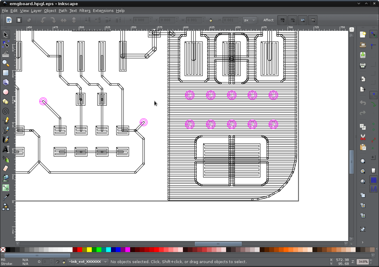
Here's the PCB layout...
Drawing the text was pretty slow, so I ultimately removed that from the raw gcode.
Here's the visualizer from the Universal Gcode Sender (UGCS) (a *very* nice feature, that definitely makes conversion to g-code worthwhile even if you have a device capable of HPGL):
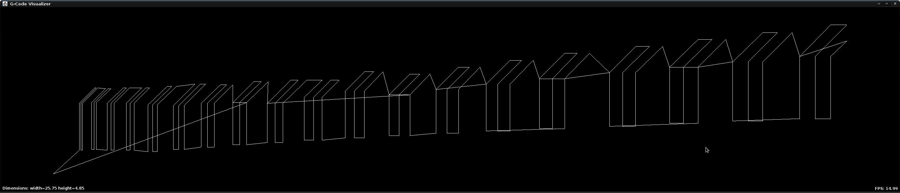
Interestingly, it doesn't draw all the paths in the same direction, guess it's trying to save time as best as possible. Also, though, it turns out to be a handy test of the precision of the system...
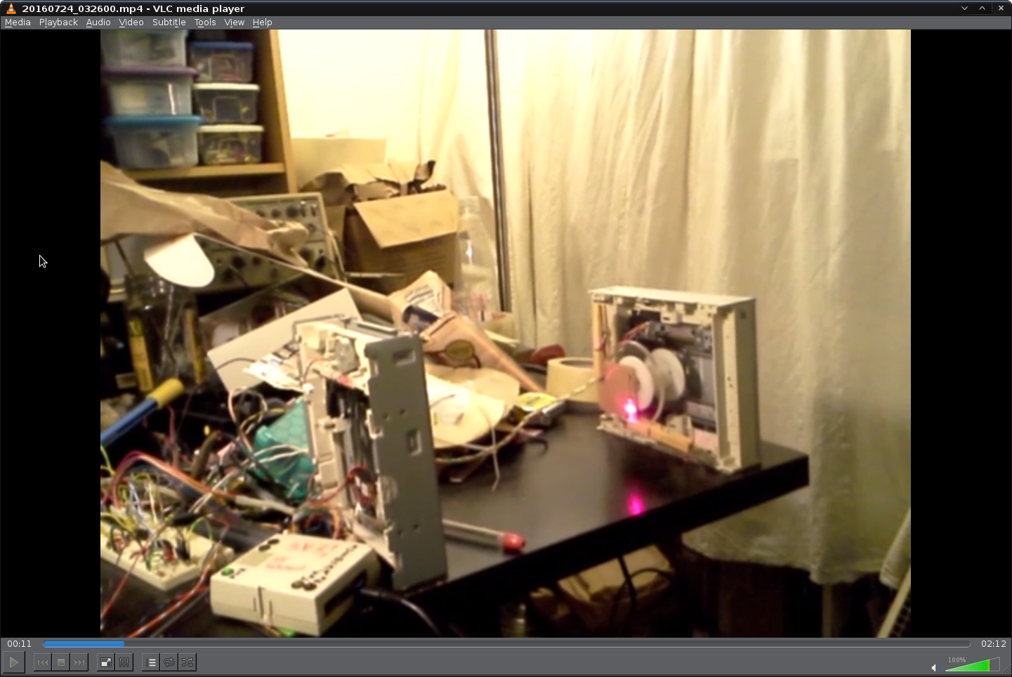
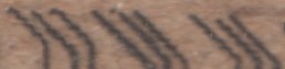
Here's the cardboard:
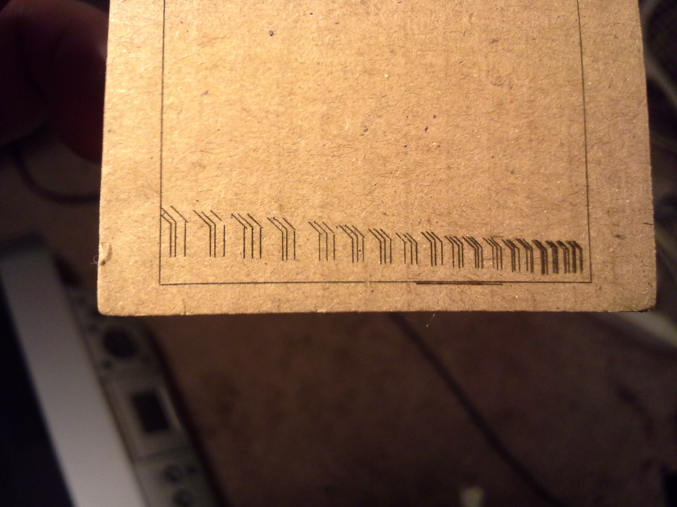
Yeah, I could expect some breaks, likely due to the cardboard fibers varying in various locations, rendering it more difficult to burn... But then there's some overlaps, and those ain't right. Then there's the traces which clearly aren't evenly-spaced... and that ain't right either.
So, I thought, hey, there's a lot of conversion going on 'round here... Who knows where it's coming from, but I can easily think of conversions from floats to ints, then back to floats, then back to ints, and probably even more. So... maybe... And then there's the fact that my PWM-based "microstepping" is pretty much non-sophisticated, but we'll come back to that.
So I spent *way too much* time trying to get a side-by-side between the actual output and the rendering... And discovered many flaws in my thought-process along the way.
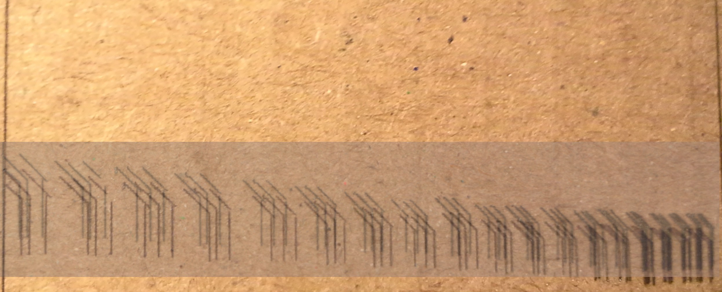
Big One: cameras taking close-ups distort the image. Below is a scan (from a flatbed scanner) overlayed (and slightly shifted upwards) atop the photograph:
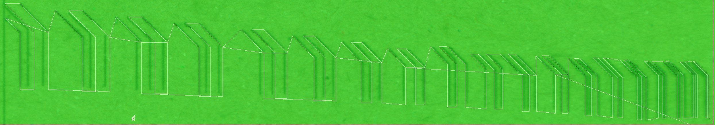
Here we have the rendering compared to the scan:
Here's a highlight:
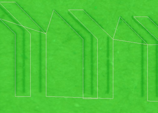
So, that might make sense, considering I modified grbl to add direct PWM-based microstepping output... microstepping isn't *particularly* accurate, anyhow. And my implementation could probably stand to be improved.
Note some other "features"... there's a distinct jagged-pattern on the diagonals. That'd make sense if single-stepping.
...So, maybe it's best to stick with dedicated motor-drivers with step/dir inputs (rather'n H-Bridges), if you've got 'em, or money, or patience waiting for delivery... none of which are on my plate ;)
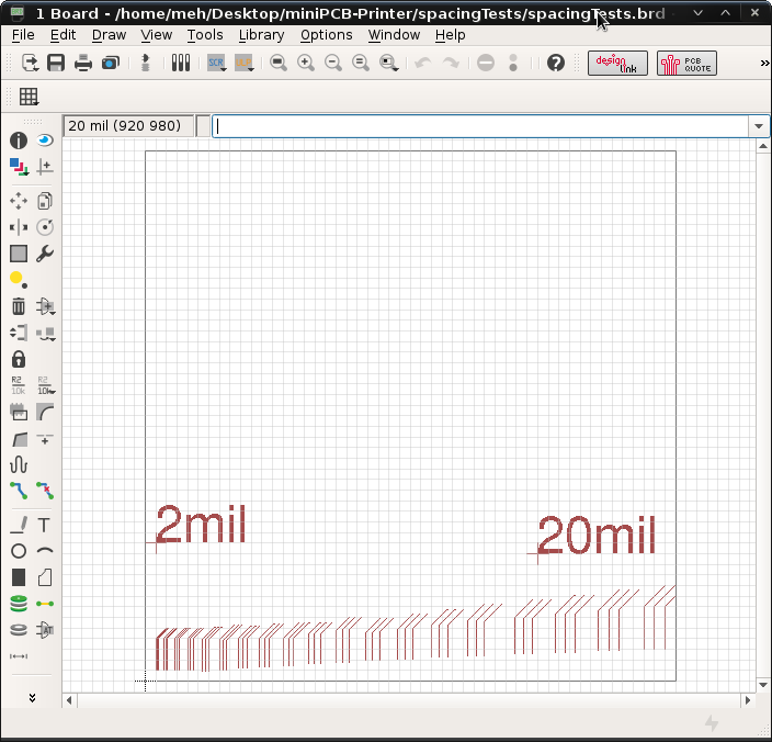
Thing is, the traces in that furthest-to-the-left group are separated by 20mils, and off by quite a bit. Worse-still, I haven't calibrated the machine, which means that those are more like 30mils! Also, those overhangs are bad, and the opening is even worse... So...
(hmm, is it just me or are those 'stair-steps" longer than they are tall...? I wonder if gravity has anything to do with this?)
Oddly... I don't recall that much error on the earlier tests which were *much* more complex...
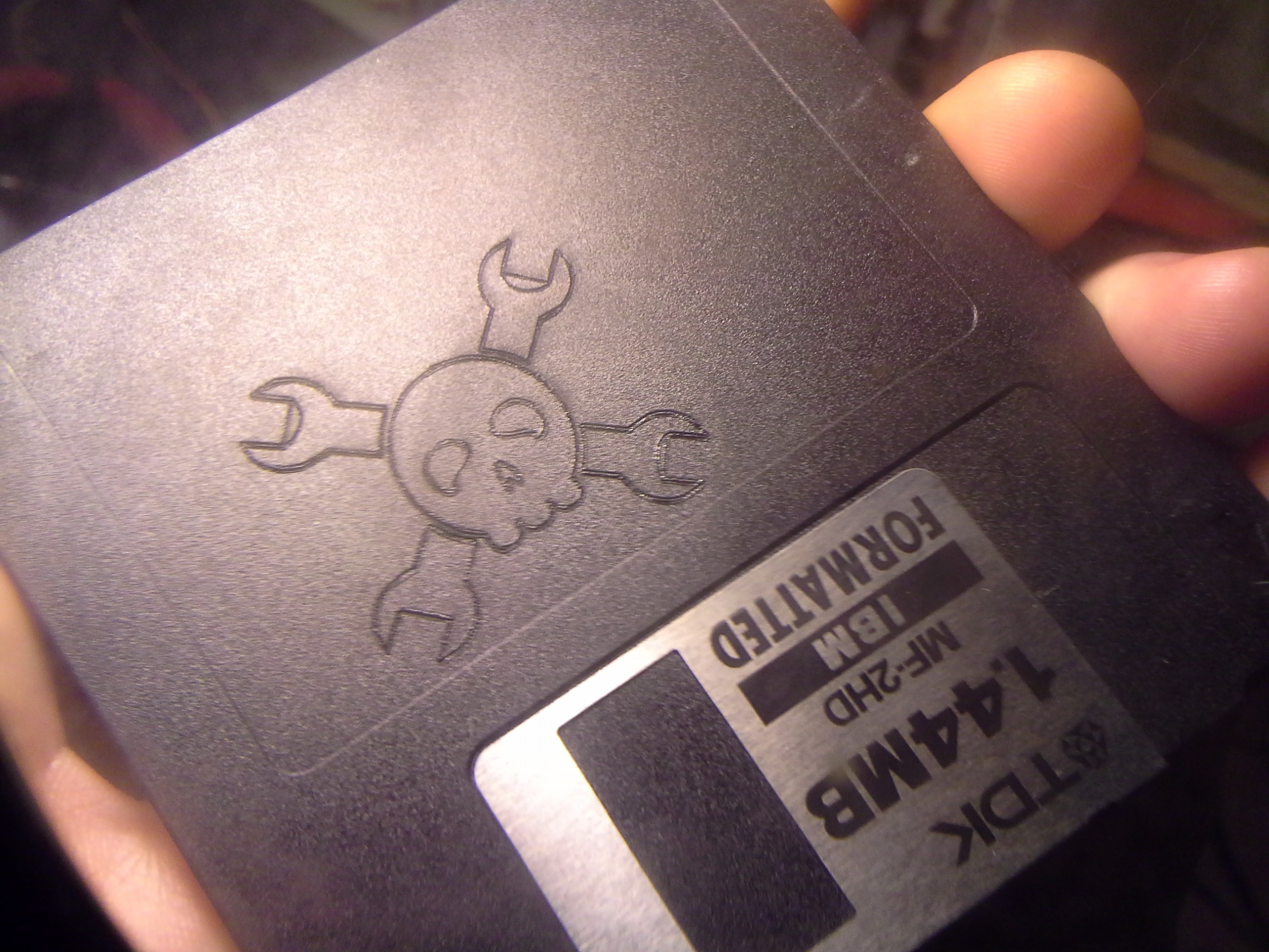 Note that this guy was drawing each line *twice* (except for those weird rounded-insides of the wrenches which I can't explain). But maybe if it drew them from the same direction each time (I'm not sure) then it would be less noticeable...
So, I'm not sure.
One plus: That "trace width" is looking like about 7mils, as best I can figure out how to measure it with my calipers.
Discussions
Become a Hackaday.io Member
Create an account to leave a comment. Already have an account? Log In.