 Eric Hertz
Alright, a tiny bit more research...
This is a good resource:
http://www.allaboutcircuits.com/textbook/alternating-current/chpt-13/stepper-motors/
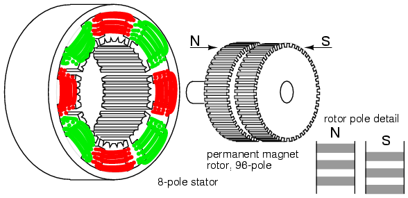
Here's a "Hybrid Stepper Motor" (simplified), (from that page):
 (simplified, further:)
"Hybrid stepper motors" are a bit more sophisticated than those in your DVD drive, but they're the ones I've taken apart, so I can understand this one a bit better. These are the big-ol' NEMA# motors used in most 3D printers. They can come in both unipolar and bipolar form.
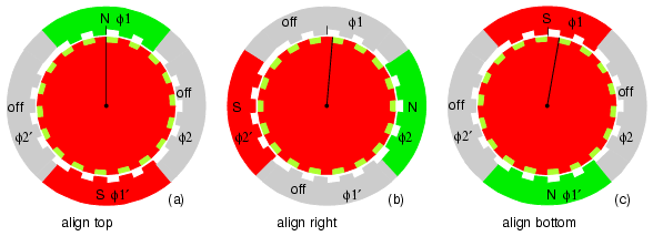
As far as a bipolar stepper motor, the rotation shown in the second image is acquired by the more-complicated form of single-stepping, described in my last log:
 As far as *typical* bipolar-driving goes, this method is less-typical, as it requires more sophisticated circuitry that not only can reverse polarity, but *also* can disable power to the windings. But let's go with this for a second, because, again, this is *much* more closely-related to the typical *microstepping* method used for bipolars.
So, what you see in the image (repeated because... scrolling. Wee!):
So, what you see in the image is the South-Pole of the rotor, and between its teeth you can see the North-Pole which is behind. Note that the teeth on opposite poles are 180 degrees out of phase.
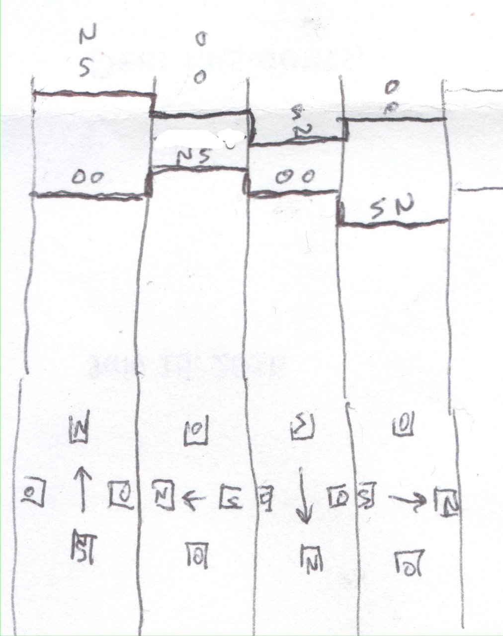
Alright, that's not much different than the simple "bar-magnet" drawing from before. I won't repeat it, here.
This image shows single-stepping where the teeth of the rotor align perfectly with the powered teeth. These positions are *strong*.
But, here's a half-step:
(This is modified from the original image shown above, from allaboutcircuits.com):
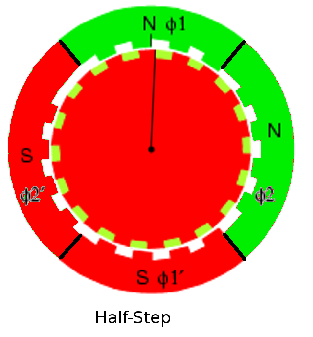
Now, consider that the teeth on the *opposite* pole on the rotor are also now 1/4 aligned with the teeth on the phase-windings. This guy is now pushing back, *against* the phase-winding's magnetic-field. So, I don't know physics to this extent, but I imagine that means it's essentially depleting the overall holding power by something like yet another 1/4th.
So, with my bar-magnet example from the previous log I guessed something like: Put in 2x the power of a single-step (by powering *both* phases' windings, instead of just one) and get something like 1.414x the holding-strength.
And, here, it seems similar might be true... Again, we do have *both* phases powered, this time, rather than a single one (as in the full-steps shown in the original image), so we should have *more* holding-power than single-stepping, but definitely less than double.
Further, when moving from one full-step into the next half-step, we have an interesting scenario where the "other" magnetic-pole is *resisting" that motion. If merely single-stepping, as in the image shown earlier from (a) to (b), *all* the magnetic-force created would go into *pulling* the rotor into its new position. Well, rather, the South pole teeth on the rotor would be pulled to the north winding's teeth (as in (b)) and the North pole teeth on the rotor would be pushed away from the north winding's teeth. So, all the magnetic-force created by the windings goes into moving the rotor to its next step. BUT when half-stepping from (a) to my Half-step image, the opposite poles are acting to *resist* the motion.
This observation isn't regarding the holding-power, but regarding the *moving* power... It would kinda *dampen* the motion... In a way that's nice, it *smooths* it a bit, rather than creating a sudden jerk between positions. But, it also means that now *time* is more of a consideration. Sure, an *unloaded* stepper would eventually wind-up at that half-step, but getting there is a slower process, a bit like pouring syrup rather than water(?).
Then, when you consider external forces, say a spring pulling the rotor counter-clockwise, it's quite likely not only will the motion be slowed even further, but that it might not actually ever reach the "half-step" position, maybe resting more around 1/4th step. OK, that'd be a consideration even with single-stepping. But, now, let's consider other factors... What about overcoming static-friction from (a) to the half-step? What about from (b) to that half-step (reverse-direction). So, now, our half-step might be inclined to go only 1/4th-way between (a) and (b) in the clockwise-direction, and will be located 3/4ths of the way, when "microstepped" in the other direction. What about momentum if the system's already moving smoothly...?
Etc. Etc. Etc.
So, this is where my intuition is telling me that using *sinusoidal* drive-signals for the phases' windings may not be the most effective approach. And, yet, it is pretty much the de-facto method, as I understand. E.G. look at this sophisticated system: http://www.edn.com/design/analog/4368829/Back-EMF-method-detects-stepper-motor-stall (the below image is from there, regarding a dedicated stepper motor driver chip):
 This motor-driver chip is designed with microstepping in mind, and uses sinusoidal current waveforms for the phases.
Remember my earlier ramblings regarding the input-power with half-stepping... Wherein we were powering *both* phases at *full power*, and coming up with something like only 1.5x the magnetic force (or less?)...
With actual microstepping techniques, at a half-step, we'd have sin(45) = sin(45+90) = .707x the power output by the motor-driver and going into each winding, so rather'n double the full-power going into the system (vs a single-step), we now have 1.414x the power going into the system, and that, again, is reduced in magnetic-force due to teeth-alignment between attracted-poles to something like 3/4... giving roughly 1x the magnetic-force... Which, would be great, darn-near-perfect (if efficiency's not a concern), except again that doesn't account for the fact that the same polarity-teeth--which are aligned by 1/4 with the same-polarity phase-windings--are *resisting* that motion, and further pushing back even when in steady-state.
This sinusoidal microstepping technique seems to be treating each [micro] step as a steady-state, and further, neglecting the half of the system.
Now, that chip is allegedly "programmable" wherein maybe they plan for other more sophisticated waveforms... I've yet to see anything regarding what those waveforms would look like. Maybe my initial guess of something more like a tangent-function is a bit off-kilter, maybe something more like a sin^2? But, still, such a system would be treating each microstep not as a *motion*, but as a steady-state...
...so, still some intuiting and searching to be done.
Oh, right... and none of this is to say anything about the types of steppers used in a DVD drive, which are quite a bit different, in design (and plausibly in functionality at this level?).

Discussions
Become a Hackaday.io Member
Create an account to leave a comment. Already have an account? Log In.