 Ted Russ
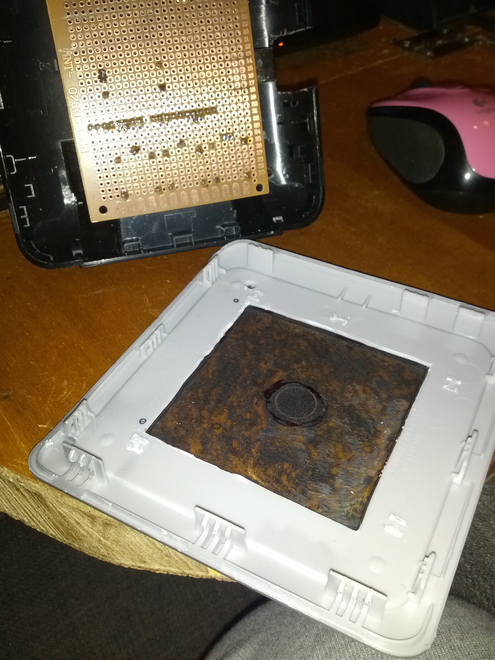
Future FEPs (Front End Processors) will add a secnd weather station on the north (warm) side of the homestead that will also monitor soil temperature and moisture, wnd speed and direction, and rainfall; and an FEP for the garden and aquaponics beds and perhaps also the water tanks and animal water and feed levels.
0%
0%
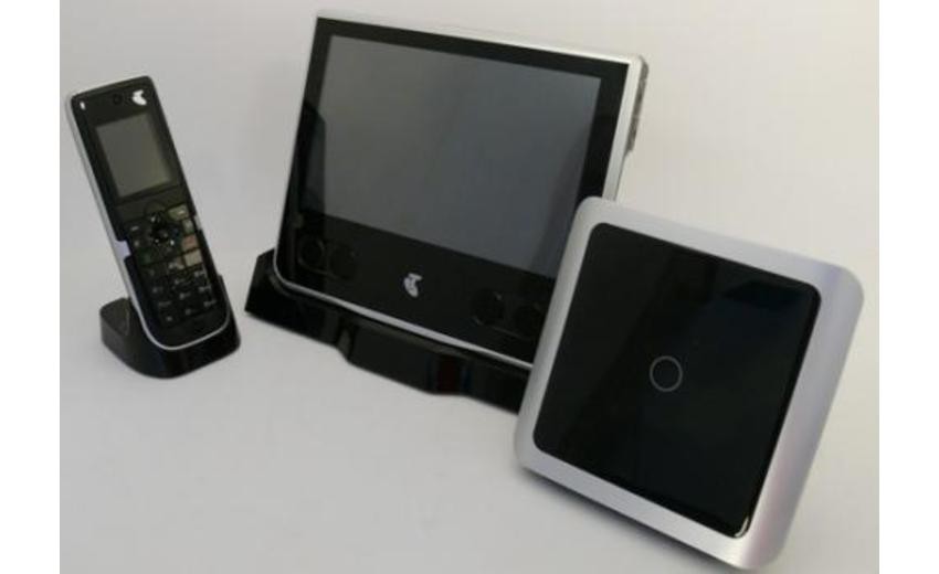
Kitchenduino FEP / HUB
Hub and FEP for a series of connected controllers and FEPs.
Become a Hackaday.io member
Already have an account? Log in.
Just one more thing
To make the experience fit your profile, pick a username and tell us what interests you.
Pick an awesome username
hackaday.io/
Your profile's URL: hackaday.io/username. Max 25 alphanumeric characters.
Pick a few interests
Projects that share your interests
People that share your interests
 Casual Cyborg
 WJCarpenter
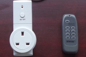
 Andy Smith
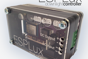
 Matt
Matt