 Ted Russ
Managed to stay thinking long enough to wire some of the shield board up. So now the relays are connected to the ULN2803 outputs, there's a 12V rail to the site where I'll put the 5V regulator for powering the relays (Uno board will supply enough oomph for the half dozen flea-power sensors) and the spots for the Neopixels have been left clear.
Time perhaps to explain the case for the project:

The thing at the front right is it. They're generally reeliable, after two years you own them, and whoever owned the one I found obviously either fried it or didn't want it.
I found that the thing is held together by internal clips that do give way to a generous flat blade screwdriver probing, and then I removed the circuit board and will probably scrap it once I know what bits I want off it.
The front panel consists of a sheet of clear plastic with black paint on the back of it glued in with double sided tape, pried that off quite easily too, and ground off most of the black paint with a Dremel. (In an area to suit the cut-out I mde and which I'll explain next.
That ring in the middle is just a clear bit left for a blue LED to shine through, the rest of the cover is solid but thin plastic with a hole for the LED to shine through. I cut a square opening out for the neopixels to shine through, and the paint removed is the same size as the hole. This also gains a few millimetres for the boards to sit inside.
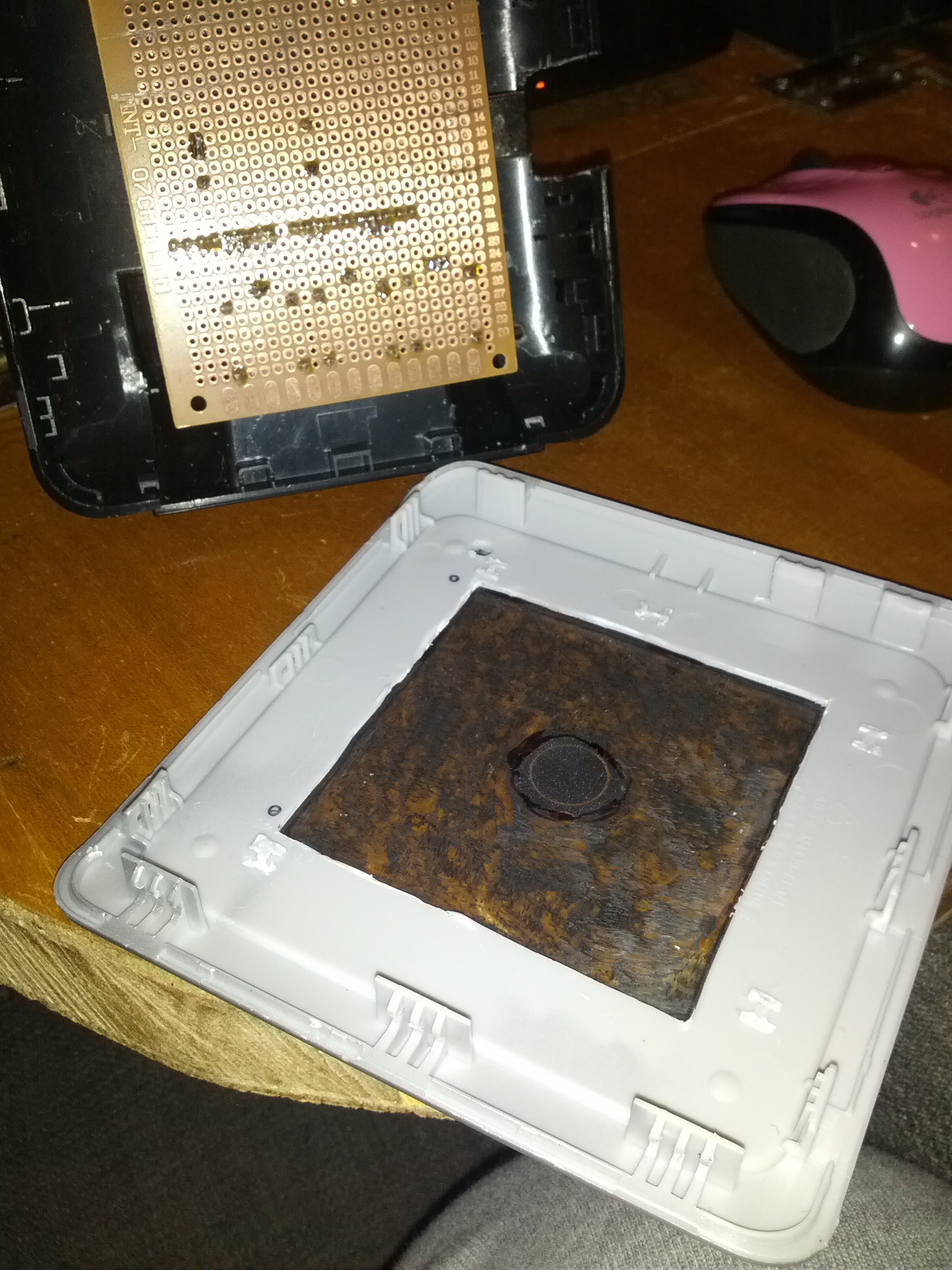
You can see above pretty much all of the steps. I still need to grind off a lot more black paint but I have the flu and the smell was getting to me so - later.
You can also see I marked two of the four holes for mounting the boards. These holes will go right through the cover and the clear plastic. Then I'll thread the M2 bolts through the clear plastic and put a nut, then through the cover and put another nut, and then the shield board, and a final nut to secure it all. This will let the Neopixels be mounted between the shield board and the clear plastic, as they're a few mm thick and then there's the wiring to consider too. I could secure the clear plastic directly back to the cover and then use two nuts to space the board - but then it may still fit inside or it may not, it's too hard to suss out so I'm playing it safe. %)
At the top you can see the back part of the case, and see that I've chewed out the right hand side where a little button arrangement used to be, The button just pressed a tac switch on the original PCB but by luck it was also right where the Arduino's USB port is, so that's one cable catered for.
You can also see the shield board, 70mm x 90mm for comparison.
I'll include the soldered shield board once I've put all the wiring on it, so for now this is it.
Discussions
Become a Hackaday.io Member
Create an account to leave a comment. Already have an account? Log In.