 lukasz.iwaszkiewicz
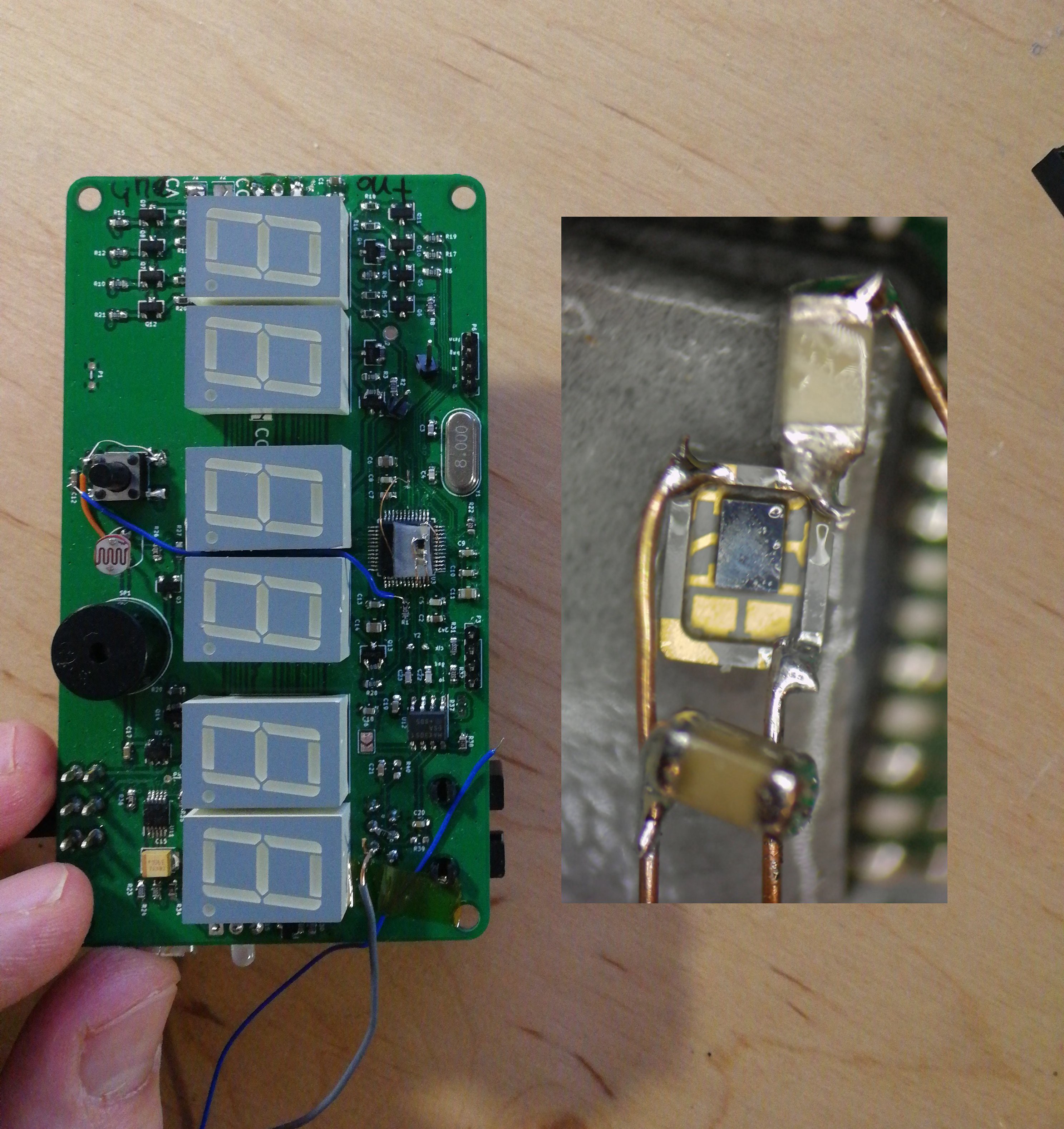
Principle of operation is very straightforward : there's a transmitter and receiver facing each other making kind of a gate. Transmitter emits IR light and receiver sees it.
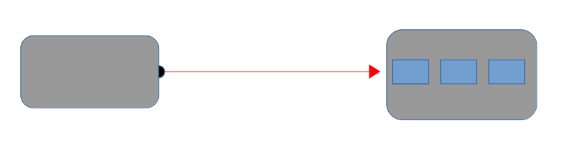
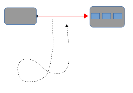
Now if an object like person, RC car, motorcycle etc cuts the beam of IR light it triggers the stopwatch and it start to count up with 1/100 s accuracy.
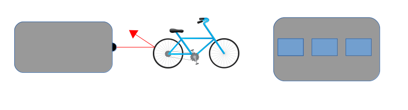
After finishing its course, the object returns and breaks the beam once again thus stopping the stopwatch.
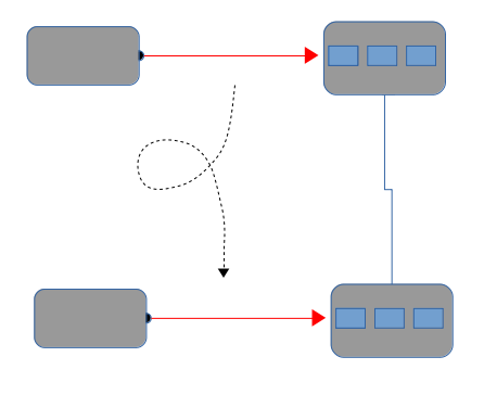
Two stopwatches can be connected together allowing non looped courses.
And here's one of early prototypes in action :
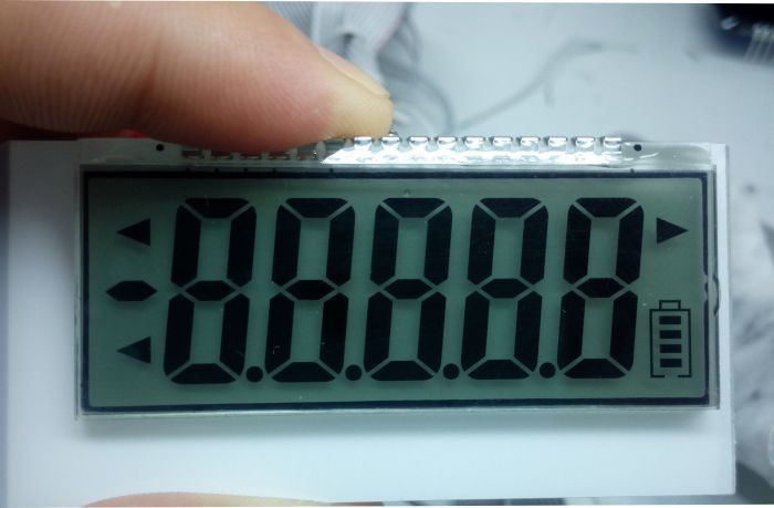
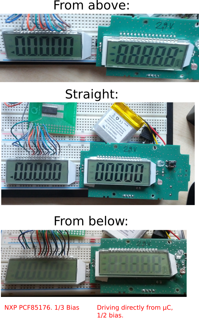 So, on the right side you have my rev. 2 prototype (second PCB layout, not counting the early bread board prototype). It is usable, i.e. one can read the LCD, but there is also significant ghosting which makes the display unreadable when viewed from angle. I tried to modify the firmware (BTW firmware is based mostly on this

 Marius Taciuc
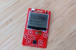
 deʃhipu
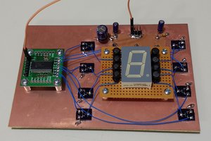
 Ted Yapo
 Gabor
Gabor
Pecka, snad slouží dobře. V současné době řeším něco podobného a kompaktního.