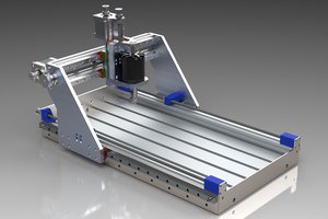
As of 9/12, I'm still in the design and materials acquisition phase, refining the drawing, especially details like bolt holes and some of the mechanics. You can probably tell on the drawing that I solved a problem that most vertical CNC implementations face: the gantry bearings and rails need to be oriented vertically rather than at the angle of the gantry. Bearings would probably do OK with sidewall pressure, but the gantry would be prone to "unclipping" itself from the rails. Using gravity as an advantage, I adjusted the angles to have the bearings ride on the rail perpendicular to the earth. But there are so many more details to work out.
OpenScad is my design tool of choice. I have some modules that I'm developing that will assist me with turning the drawing into parts cut lists, complete with dimensions and angle measurements. If you use OpenScad for your designs, you know how difficult it can be to take a cool drawing and turn it into parts that you can actually print or mill. So, this project is more than just a Plasma CNC build, isn't it? Oh well.
 andrewwjtoler



 Oscar S.
 Roger
Roger
 Nishant Agarwal
The "slugs" are going to be a huge problem.....they'll close the kerf off and could wind up swinging so it jams the motion system.
Which is why the machines are horizontal.
You do realize if you turn it around as drawn in the isometric-ish sketch, and put a hinge on it, it would take up almost no room and you could swing it down like a Murphy bed when you want to cut something?
Gravity is going to make you its bitch vs vice versa.