 jupdyke
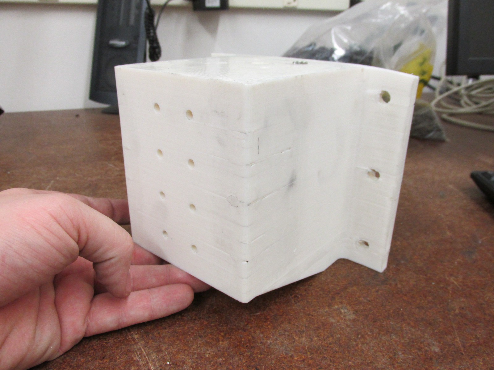
I finally got around to machining a new spindle mount. I 3d printed one a while back to help figure out how everything would fit together. I knew I wanted an aluminum one, but I used the 3d printed version to get the spindle mounted, figure out the connection to the motor, hooking up the tachometer and working on the Z axis.
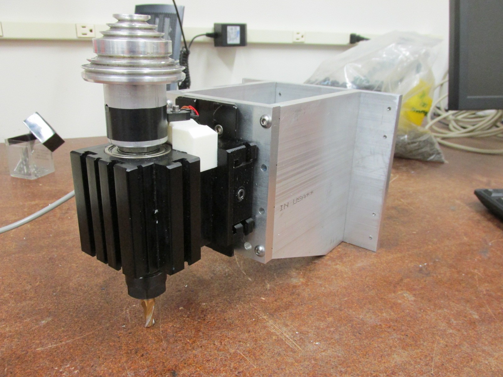
Now that most of that is worked out it was time to make an aluminum one. I started with some 3/8" thick aluminum. Then cut it down to rough shape on the horizontal bandsaw. Next I finished the size and drilled all the holes. Most of the work was done on a manual mill using the normal vice. But to drill the holes in the end I clamped it to a right angle plate. Nothing too complex about the design. I will probably put some thread locker on the screws at some point. But I want to get it together and working before I do that.
Plastic Version
New Aluminum Version
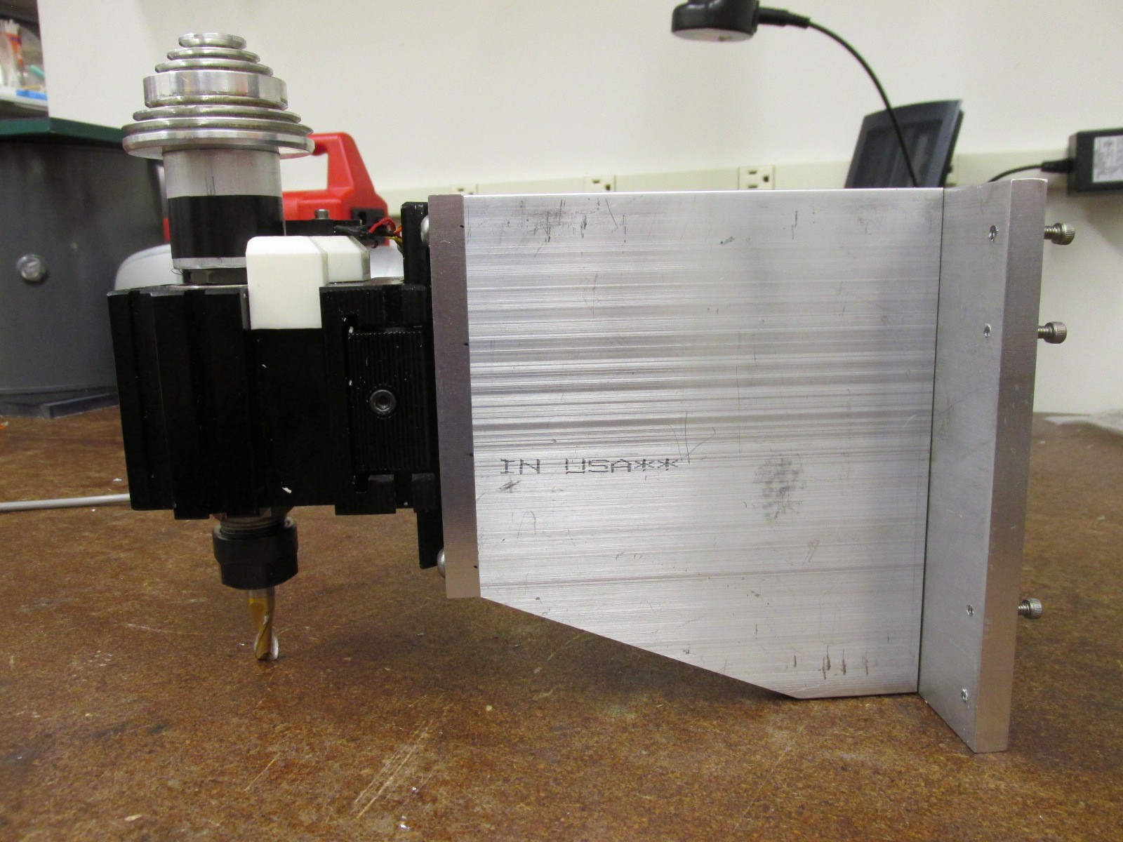
Side View
Top View. I only have one bearing screwed on to test the fit. I am waiting for some screws to come in the mail.
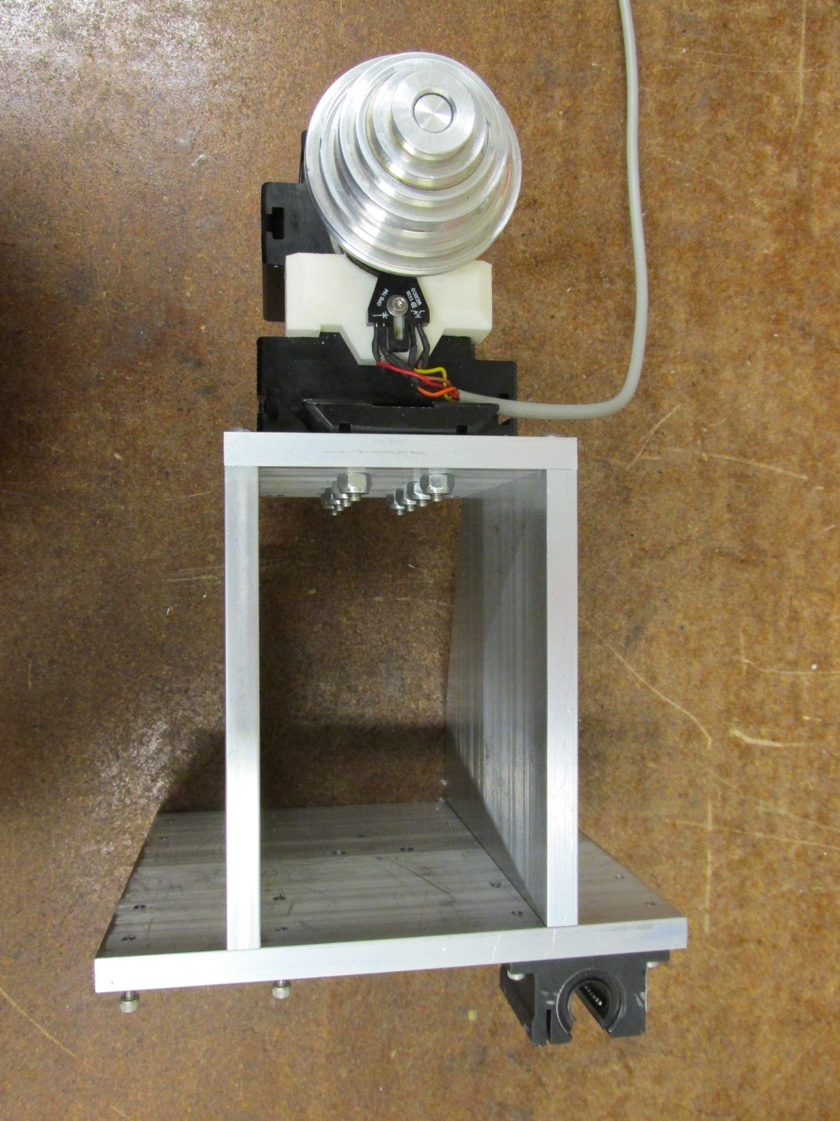
Here you can see the spindle encoder. I 3d printed a small bracket to hold the sensor in place. There is a small reflective sticker on the spindle shaft. This will give me an accurate feedback of the spindle RPM.

Discussions
Become a Hackaday.io Member
Create an account to leave a comment. Already have an account? Log In.
Jan,
Thanks for the advice. In building this machine I already have a lot of upgrades that I want to make. The rails and bearings are on that list. The bearings and rails that I am using were salvaged off of some random project my university was getting rid of. So I designed the machine around the parts that I had.
I would love to see pictures of the machine you are building.
Josh
Are you sure? yes | no
Congrats on the machining here. I am working on the second version of something similar, using both supported and unsupported rails. Would like to note that the distance between the rails of the z axis and the tool / spindle in your design is quite long compared to the distance between the bearings. Also supported rails in this orientation is not at it's strongest due to the contact angle of the spheres inside the bearing blocks.
My current machine has a somewhat similar aspect in the y-axis and it's causing resonance when milling as the long arm reduces stiffness.
Have you considered inverting the bearings and rails of the z axis ? Put the rails and stepper on the spindle and the bearing blocks on the fixed column ? That way you would be able to bridge the necessary distance and keep the bearings much closer to the spindle.
Also i think that unsupported round shafts have an edge over the supported ones for relatively short distances typical of z axes, due to the extra row of spheres and closed / round design.
Are you sure? yes | no