 Andrew Starr
I had a false start with the first prototype core array, where I discovered that my core orientations and sense wire threading pattern were picking up noise from half-selected cores, causing the sense amp to register non-existent core transitions. I've redone the array wiring in such a way that the orientation of the cores and the path of the sense wire through them results in the half-selection signals cancelling out.
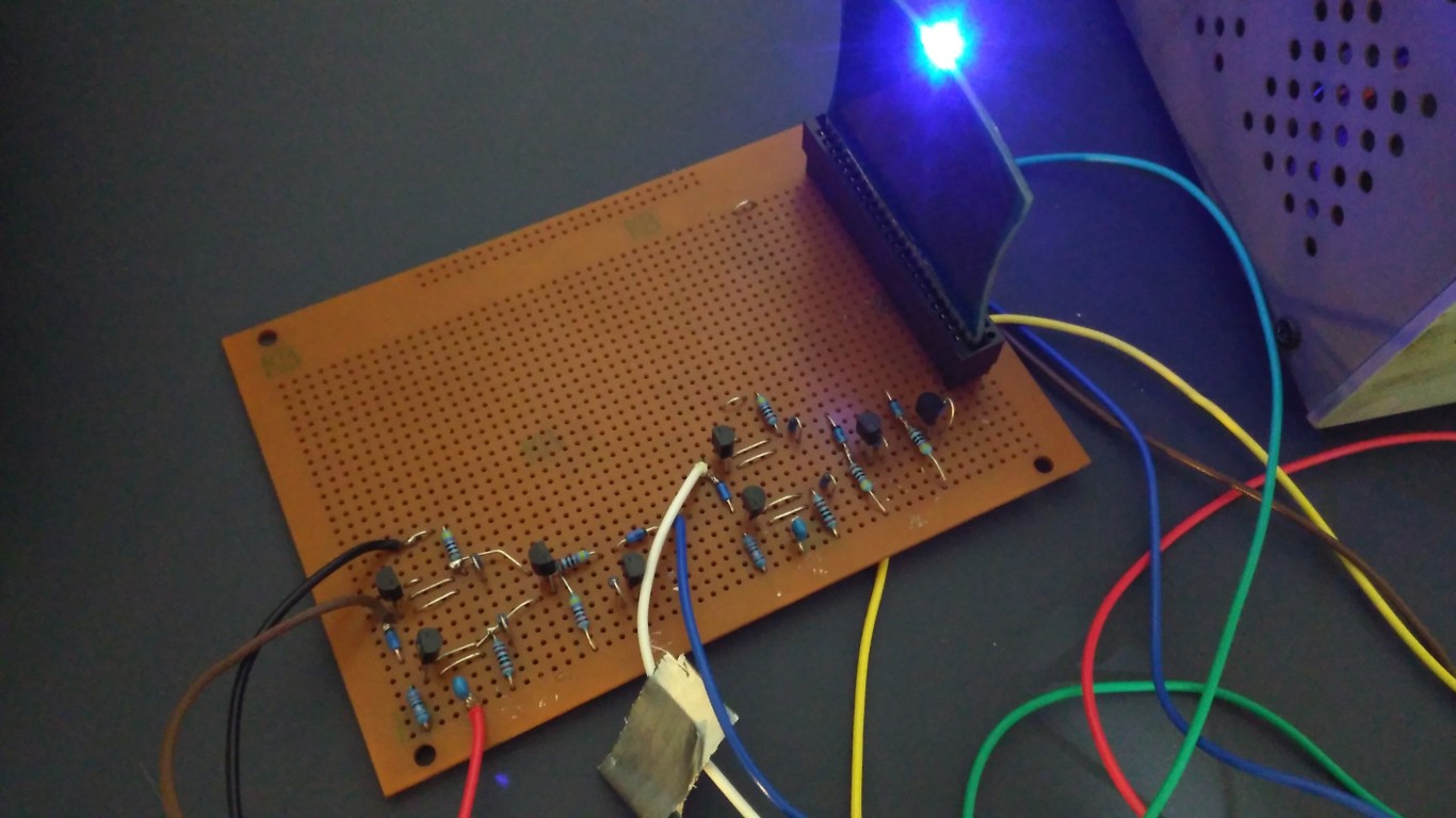
Here's a photo of a 'new pattern' array:

To date I have wired 8 core arrays, so I have enough for 1 complete 64-byte memory module.
I've also prototyped a core selection module. This module will take as inputs an active low signal (one of the row/column selection bits), and a control bit (which will determine what the polarity that the selected drive line is driven in). It is effectively a modified dual 2-input NOR gate. The inputs are common to both gates, and one gate has a PNP transistor where the other has an NPN, so they will respond to opposite polarities of the control bit. The 2 gate outputs go to the 2 drive inputs of the H-bridge controlling a particular row or column drive line. There is a selection circuit and H-bridge for each of the 16 drive lines.
The question is then, would the core selection circuit, H-bridge and core array all play nicely together? I hooked them up with an arduino to generate the control bit and selection signals. I further added a D-type flip-flop module to capture the output from the sense amp:
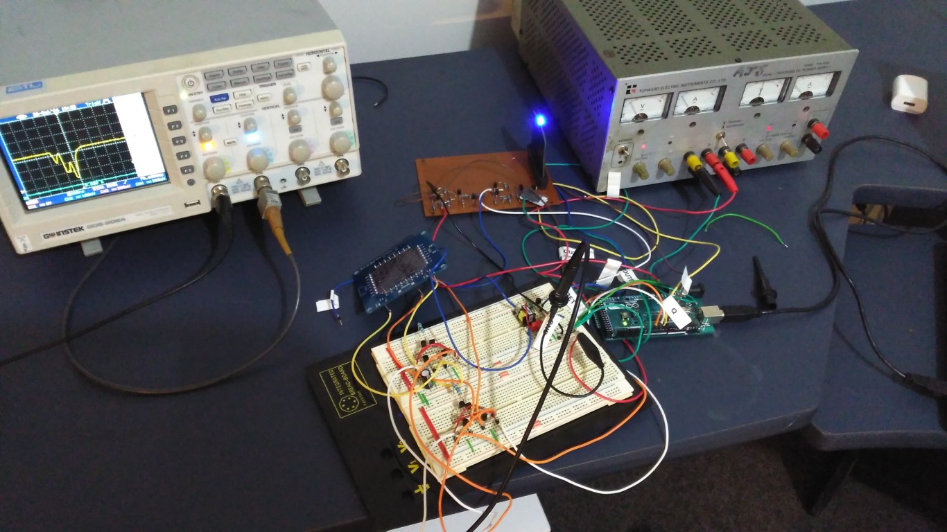
So we have:
Arduino -> core selection -> H-bridge -> core array -> sense amp -> flip-flop -> Arduino
I wrote a small program to have the arduino to continuously write a '0' to the core array, then read the array, write a '1', read the array, write a '0'...etc...and report an error if what was read didn't match what was written.
...and success! It seems to work extremely reliably, on all the cores that I have checked. Disconnecting either of the drive lines to the selected core causes errors to be generated, which verifies the coincident-current mechanism that is the basis for this type of memory.
The core switching takes about 1.25us, which seems about right.
To do next:
- build the 8 core planes into a complete module and repeat the arduino test - the planes will be wired in series and I want to make sure this doesn't cause any issues
- test the functionality of the inhibit lines
- build up core selection, H-bridge and sense amp modules
- design and build the memory module carrier board
Discussions
Become a Hackaday.io Member
Create an account to leave a comment. Already have an account? Log In.
The pictures are HUGE and firefox refuses to display them :-/
Can you reduce them to about 1000px wide ? this will also save bandwidth. Thanks :-)
Are you sure? yes | no
ok done
Are you sure? yes | no
it works MUCH better :-) thanks !
Are you sure? yes | no
Yes indeed. Have a look at this:
http://www.cs.ubc.ca/~hilpert/e/coremem/#stack
Are you sure? yes | no
that link is very good, you should include it in the details of #Ferrite Core Memory Module :-)
Are you sure? yes | no
Excellent idea. Done.
Are you sure? yes | no
"the planes will be wired in series" ?
Are you sure? yes | no