 Andrew Ferguson
In the previous log entry the static interference pattern was reported using one fixed mirror and one mirror mounted on a DVD voice coil, this mirror could in principle be moved but controlled motion wasn't yet investigated. However, plenty of uncontrolled motion (vibration) could be seen, this vibration problem has now been temporarily solved by placing the Michelson directly on a tiled floor.
Now onto the next stage. A maximum current of 330 microamps is passed through the voice coil using a digital output pin of the Teensy 3.1 in series with a 10 kOhm resistor. Since this is a PWM output the current can be varied from zero up to its maximum value, and I will do this in 256 steps. From inspection I expected about 60 microamps to give a wavelength of displacement, so it should be possible to move over several interference fringes.
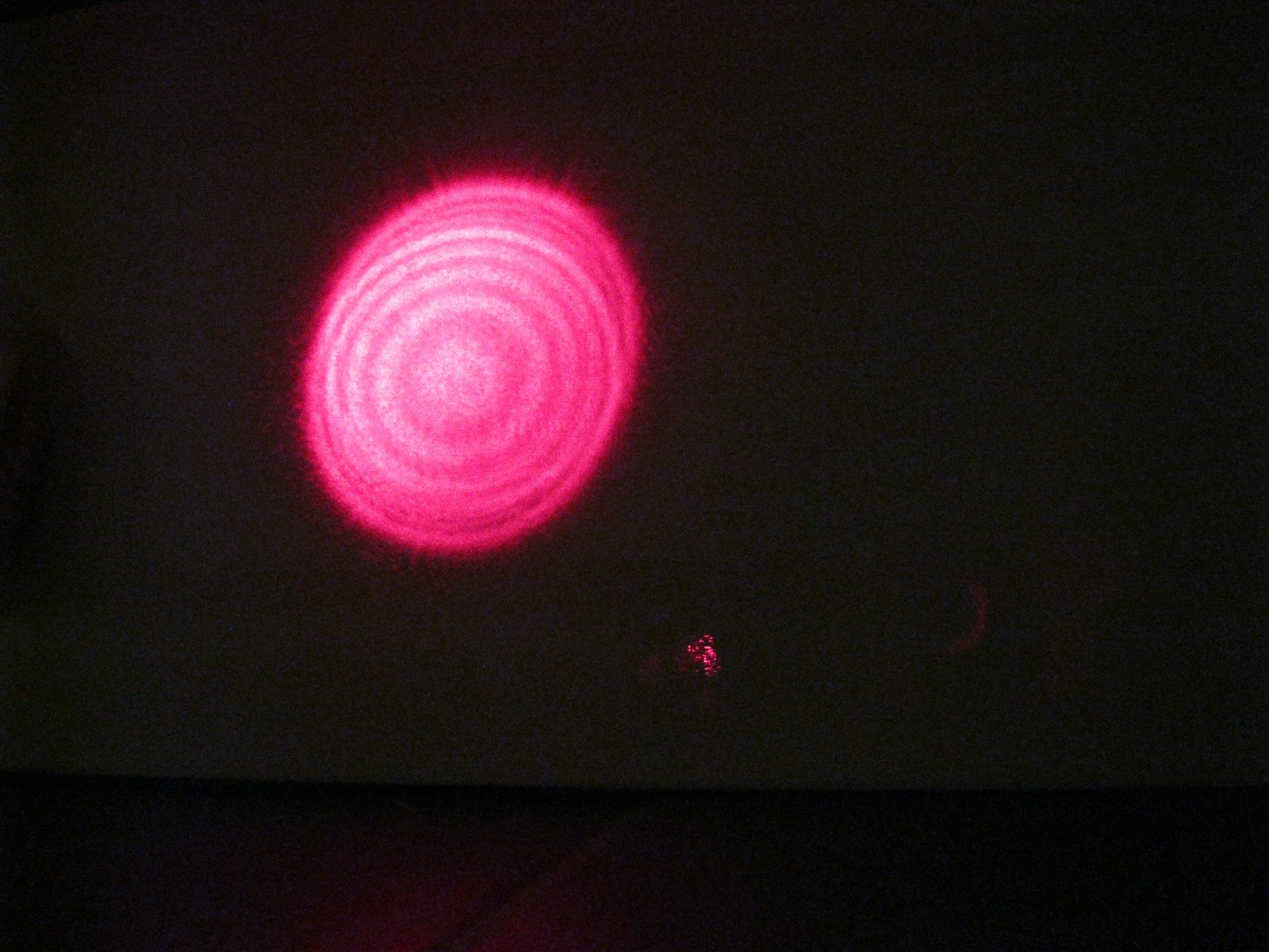
A way of recording the fringes is also needed and here I use a OPT 101 photodiode and integrated transimpedance amplifier, in this case the gain is set by an external 100 kOhm resistor but actually it would have been better to use the internal 1 MOhm resistor, to achieve more gain. The area of the photodiode is 2.3 x 2.3 mm and I place it at the centre of the interference pattern which is about 60 mm in diameter. The photo below shows the interference pattern again.
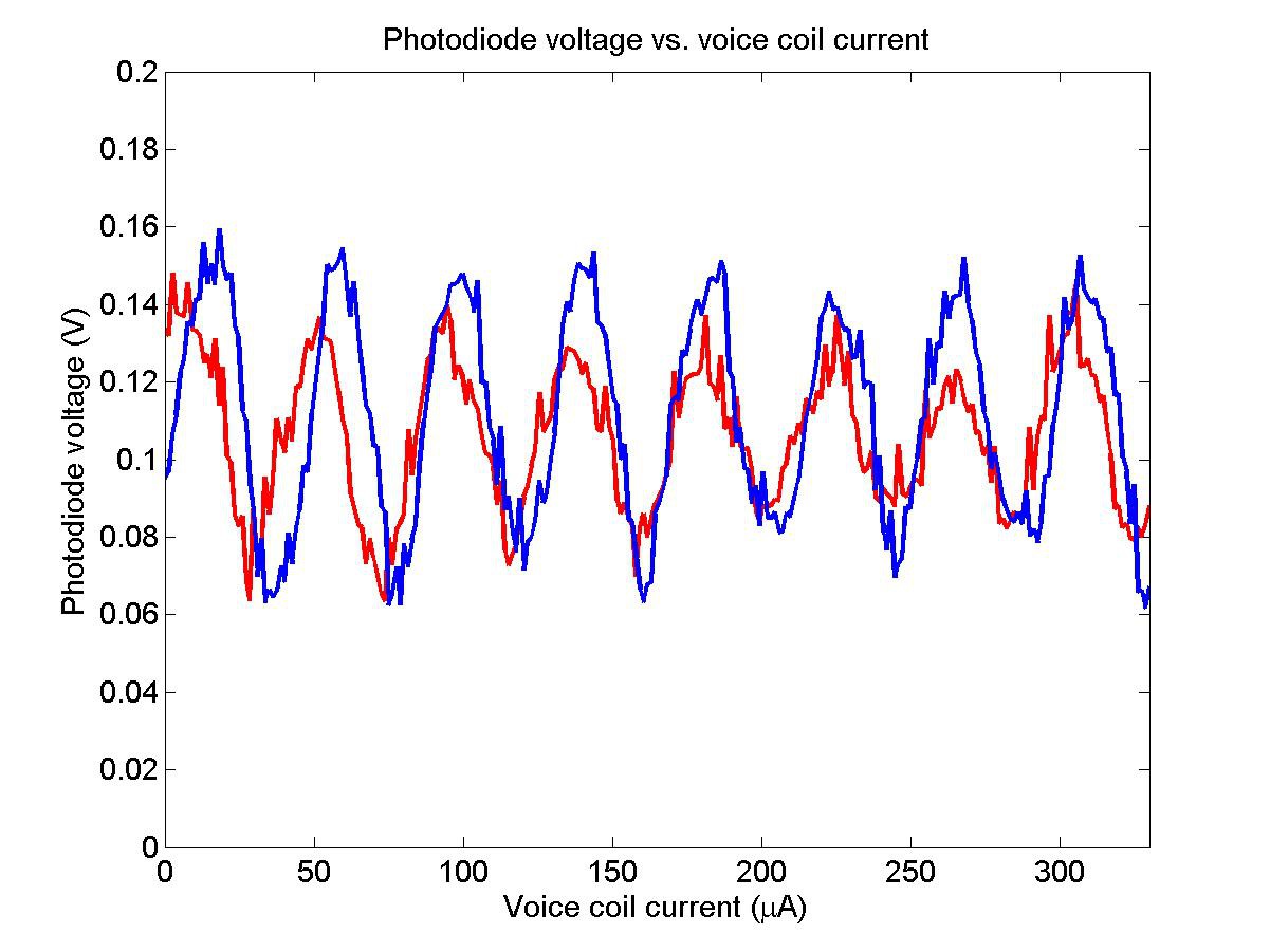
My experiment goes as follows. The voice coil current is held at 0 microamps for 10 s, then it is ramped to its maximum value over 256 steps holding at each step for 100 ms and during this time recording the photodiode voltage using the Teensy ADC. The following graph displays two successive traces, showing 8 interference maxima and reasonable consistency between runs. From this data it is seen that the voice coil moves a wavelength (650 nm) about every 40 microamps, near the estimated value. So each data point is separated by 1.3 microamps corresponding to a mirror displacement of only 21 nm.
I'm quite excited that the path length control works so well. This implementation of the Michelson now enables precise distance, current and acceleration measurements and, after some further optimization, I will look into these aspects of the instrument.
Discussions
Become a Hackaday.io Member
Create an account to leave a comment. Already have an account? Log In.
Excellent! I have put my coils in series with a resistor to get finer precision, but I would like to see a solution that works over the whole range of motion. One thing I'm not sure about is how you're using PWM to provide an adjustable current --- the coils have a very fast response rate, so are you just supplying an even faster PWM signal?
Thanks for sharing, I know this is an old project but I really like what you did with it.
Are you sure? yes | no