 Andrew Ferguson
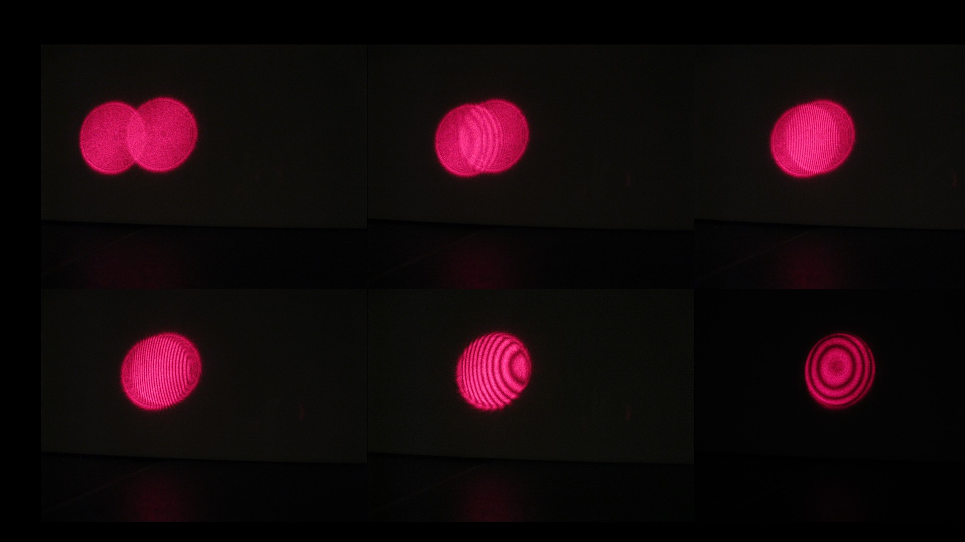
The interference fringes seen with the Michelson depend on a number of factors. Using the static, but angle tunable, mirror mounts I thought it would be interesting to take a sequence of photos as the mirrors were brought into alignment.
In the most misaligned image (top-left) two red circles are seen and there is initially no evidence of interference - the signature that light is a wave. As the mirrors are progressively aligned, linear interference fringes start to appear (see top-right), with the fringe separation depending on the relative angle between the mirrors. As the relative angle between the mirrors is reduced, the fringes appear to take on a hyperbolic character (bottom-left to bottom-middle). Finally, when there is close to zero angular misalignment, circular fringes are seen (bottom-right).
Actually, we only see the circular fringes since there is a difference in length between the two arms of the interferometer. If there were no length difference the bottom-right disc would be purely light or purely dark.
As a side comment it is interesting to note the angular precision achievable with the mirror mount. A set of three M2 machine screws are used to control the angle of the mirror, and from the images we can estimate that that it is easily possible to align to within 1/20 of a disc. The discs are 40 mm diameter and are projected onto a wall 500 mm away from the Michelson. This gives an angular precision of better than tan-1(2/500)=0.2 degrees.
Discussions
Become a Hackaday.io Member
Create an account to leave a comment. Already have an account? Log In.