To keep things easy for the judges, this post contains links to all the requirements of the Hackaday Prize Semifinals. It will be updated as progress is made, up to the deadline (Sept. 28).
- Video: Princess Sparkle and I have been working on our semifinals video for the past week and a half, and we are now finally satisfied with it. Enjoy!
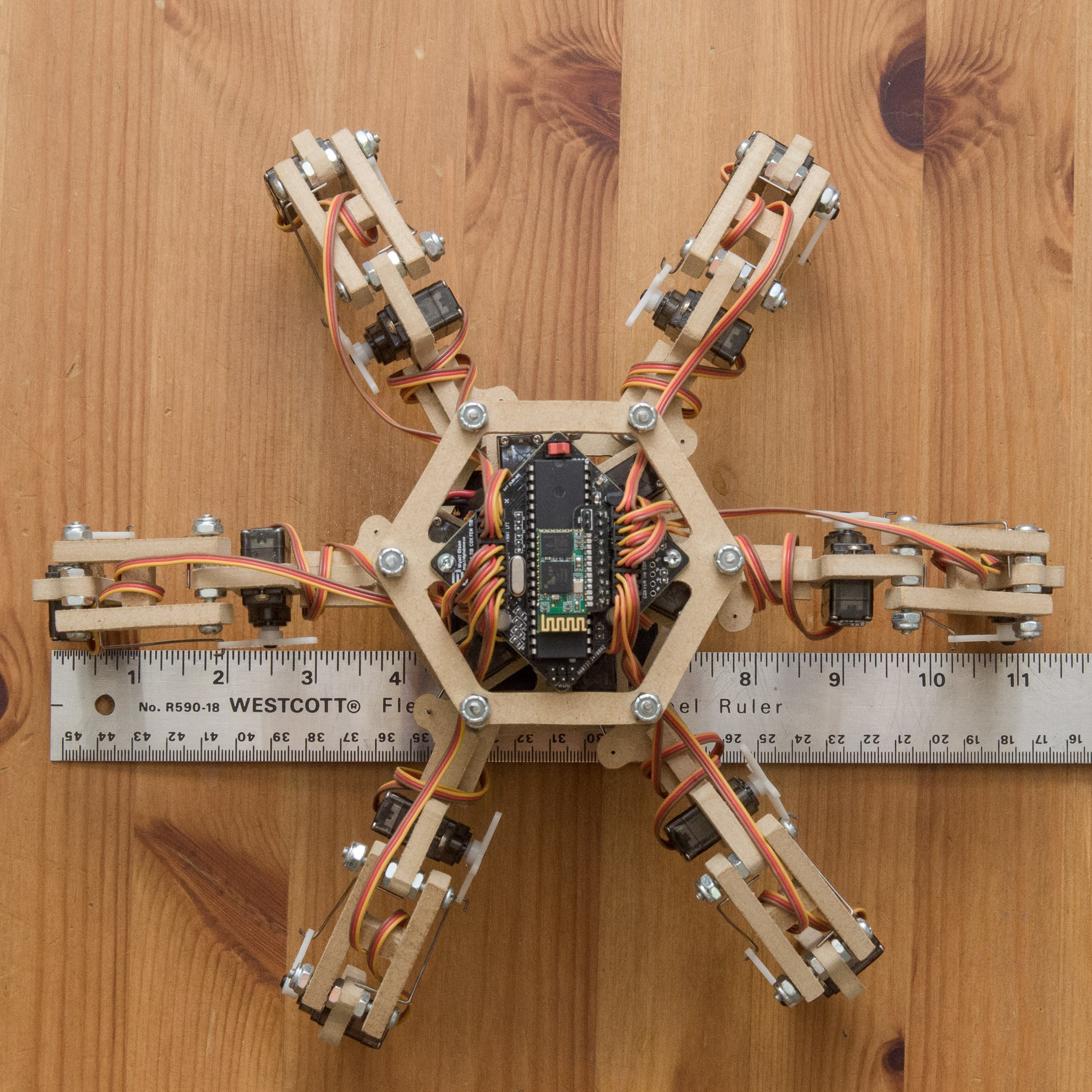
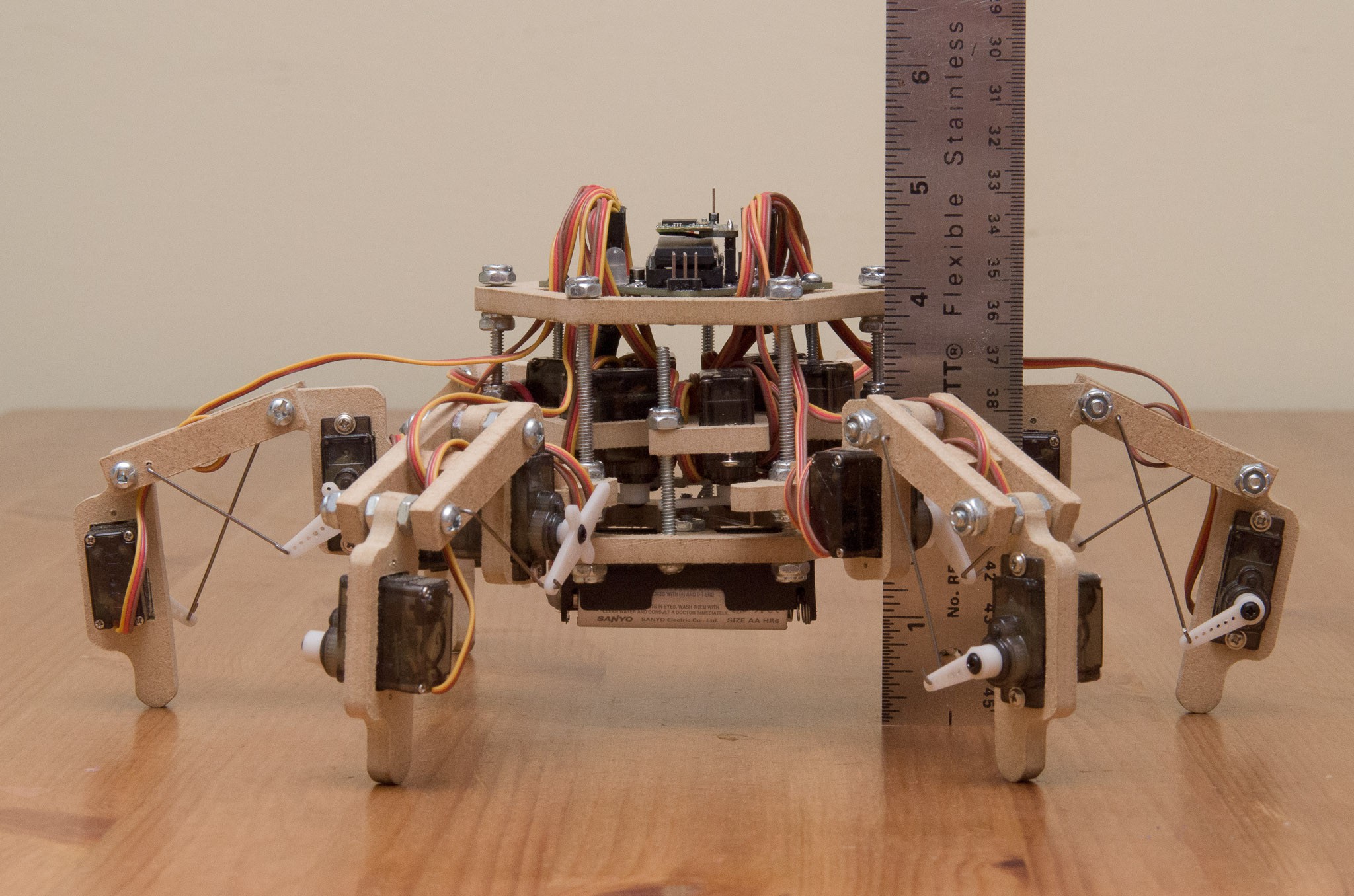
- Finished Product (Frame): The frame design of Stubby is finished; if one were to make a commercial product from these designs, it would most likely be laser cut plexiglass or similar instead of hand cut MDF, but the shape and dimensions would be identical. As indicated by Mike, since the design is finalized, it is fine to show a picture rather than an artistic rendition. (The only physical changes remaining are minor ones: an updated PCB with surface mount components, and a slightly different layout for the top body layer to accept the new PCB, which has mounting holes in different locations). Below are top and side views of the robot, with a ruler for scale:


- Finished Product (Electronics): The board you see in all the pictures and videos is the Revision 1.0 board. This board uses through hole and large SMD components, and is solderable by hand. There are newer versions of this board (rev 2.0 and 2.1) which use smaller SMD components; 2.1 even has an on-board magnetometer, so that you don't need to buy a standalone board. A commercialized version of Stubby would utilize the rev 2.1 board, which has been designed to be easily manufacturable (no components on the back, ready for pick and place machines, etc).
- Connectedness: Stubby is designed to be link agnostic. Any serial connection can be used for control. I personally have used HC-06 Bluetooth modules and XBee radios. Revision 2.x of the board includes a standardized 6 pin header with the FTDI cable pinout (which would allow users to plug in directly using a USB serial cable for testing), along with breakaway adaptor boards which allow the XBee / HC-06 boards to plug in directly. The rev 2.x boards allow users to configure the serial module to run at either 5v or 3.3v for the ultimate level of compatibility with existing hardware.
- System Design Documents: There are a few of these. The Frame Plans are printable plans which can be glued to a piece of MDF and cut with a scroll saw (PDF, DXF). The System Communication document describes how the Processing library and the Universal Controller both talk to Stubby, and describes the protocol and the most common command messages. The Electrical Schematics (revision 1.0) and Board Layout describe the circuit as currently implemented (KiCad, Gerber). (The revision 2.0 boards have been ordered but have not yet arrived and so are untested; if you are interested, you can see the schematic, board layout, and gerbers for this version too. Functionally it is very similar; the differences are a new power supply to allow the 5v ultrasonic rangefinder to work, more capacitors for filtering the large power drops encountered when running 18 servos, and many more surface mount components). Build instructions and components lists are available on the Hackaday.io page as well as (more legibly formatted versions) on my web site.
- Licensing: The entire Stubby design (including the frame design, schematics, board layout, software, Processing library, etc) is released under a Creative Commons Attribution Share-Alike license. The source for life, the universe, and everything (at least everything which is related to Stubby) can be found by browsing or cloning my git repository. (On a somewhat related note, all software used for the design, manufacture, and programming of Stubby is also open source and cross platform. This includes the Processing framework, KiCad, QCad, avr-gcc + avrdude, git, ant, etc).
- Innovation: To my knowledge, Stubby is the least expensive (~$150 at quantity 1) and easiest to manufacture (no laser cutter, 3D printer, or CNC required) hexapod with 3 degrees of freedom per leg. To keep costs down, I used cheap micro servos rather than the more expensive robotics servos. With a traditional hexapod design, the servos are directly connected to each leg segment. This requires a lot of torque to move the leg segments, and would not be possible when using micro servos. By using push rods, I trade movement range for torque, allowing the use of cheap servos. In addition to the servos, I have kept the cost of electronics to a minimum by driving everything with a single cheap microcontroller (other projects tend to use dedicated servo control boards). A hand written PWM library (including assembly code for the time-sensitive ISR) allows this microcontroller (running at only 12MHz!) to control all the servos while, at the same time, performing complex trigonometric calculations in real time. Keeping costs to a minimum is very important for my Hackaday Prize goal of teaching children programming, as that is likely to be much closer to an educational institution's (or a family's) budget than a traditional hexapod design would be.
- Reproducibility: There are a number of hackers worldwide who are currently working on their own versions of Stubby. Some have already finished, others are well underway. I have many project log updates which detail the progress of these third parties.
- User Experience / Interface: The Processing API is central to this project. I am making an effort to keep this as simple as possible, while still retaining the features needed for exploring procedural and event driven programming. While today the Stubby library is installed manually, once it is closer to completion I will submit it to the browsable list of libraries available directly from the Processing API. Furthermore, with Stubby's flexibility in communication, it can also be controlled by hand using a Universal Controller (which in my case is just a hacked PS2 controller, but could be pretty much anything that sends the proper messages over the serial port). When using the Universal Controller, I use the same control techniques that are used in video games (e.g. movement, strafe / sidestep, turning, etc). If you pass the controls to pretty much anyone between the ages of 4 and 60 they have no problem figuring out how it works within seconds.
 The Big One
Discussions
Become a Hackaday.io Member
Create an account to leave a comment. Already have an account? Log In.