The Big One
-
Revision 2.0 Boards Arrived and Soldered
10/07/2014 at 06:39 • 0 commentsWhen I got home from work today, I was thrilled to find the package from DirtyPCBs in my mailbox. They have yet again outdone themselves; I received 12 boards, all of which appear to be perfect. (If anyone in USA / Canada wants to try their hand at SMD soldering, drop me an email: $1 / board plus $4 shipping (for up to three boards). Outside of USA / Canada the shipping prices probably don't make sense to buy from me, you are better off ordering directly from DirtyPCBs).
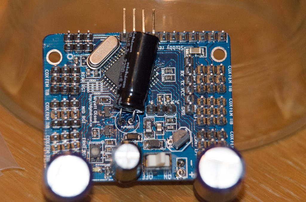
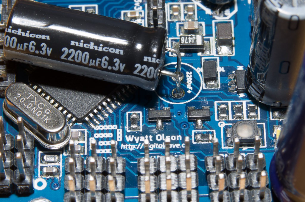
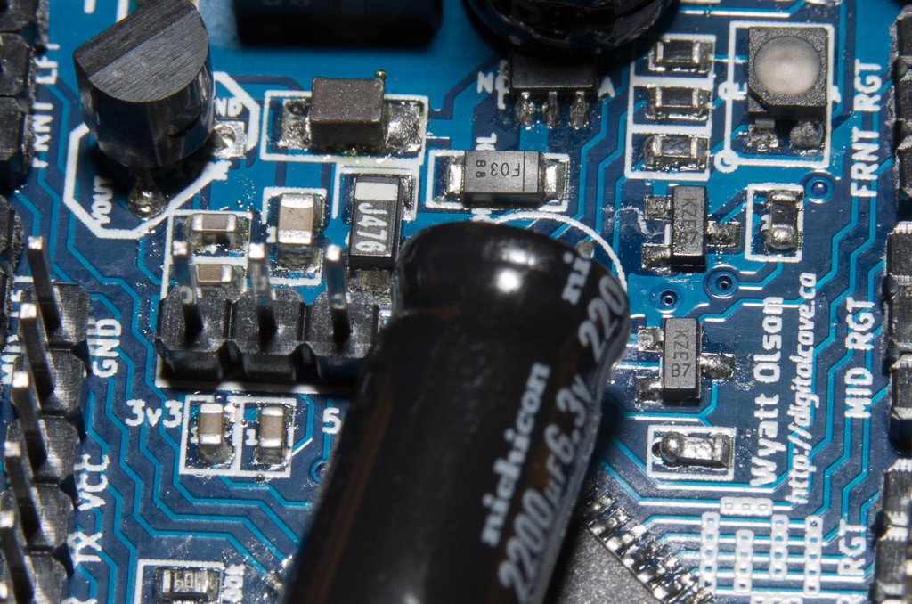
After putting the kids to bed, I started on the soldering. The SMD parts were first, and I took a video of my progress. The SMD bits took about an hour, including applying the solder paste and reflowing it using a heat gun. This was my second real attempt at reflow soldering using this method (I had done a couple of test boards, but I did one 'real' board with a TQFP-32 chip; this one is the second, with more components, tighter spacing, and a TQFP-44 chip).
I consider this attempt at reflow soldering to be a success; there were three solder bridges on the AVR, but a bit of desoldering wick removed all of them, and the AVR is recognised by my usbTinyISP and is able to be successfully programmed (I programmed the fuse bits already, and as soon as I get the rev 2 pins mapped, I will actually program the thing).
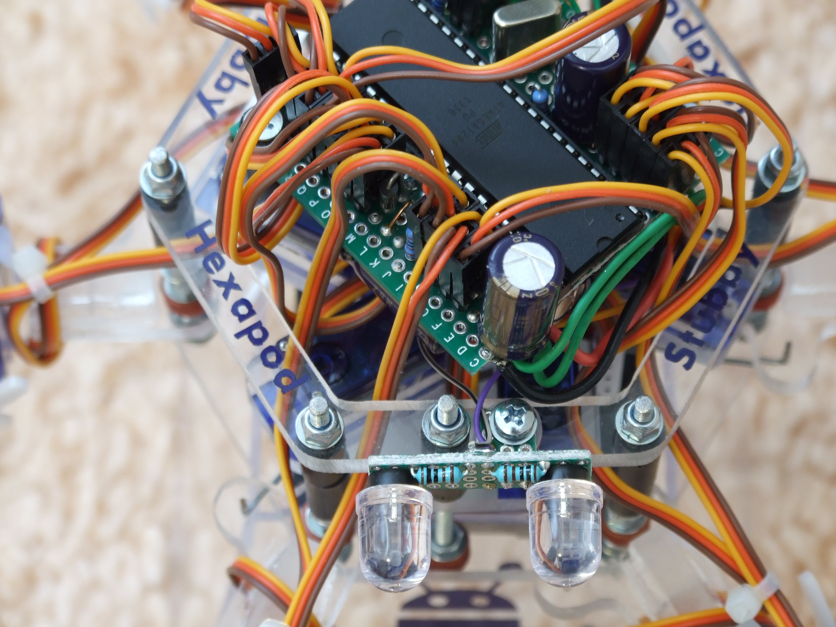
Once the SMD components were verified to be working, I soldered the rest of the through hole components, which took another couple of hours (surprisingly, I think that the through hole stuff actually took longer than the SMD work... I guess that there are just a lot of pins):
![]()
![]()
![]()
![]()
Next steps are to:
- finish writing the rev 2.0 conditionals in the program (even though the logic is the same, the pins are all different)
- cut the new top layer which fits the rev 2.0 PCB + magnetometer
- figure out how best to attach the distance sensor
- program the distance sensor
- put the whole thing together and see if it works!
Cheers
-
Petr's Build Completed
10/05/2014 at 18:52 • 2 commentsPetr H.'s plexiglass Stubby build is now complete and working beautifully. A video and some pictures are included below (all media in this log entry (c) Petr H., and used with his permission)
![]()
![]()
![]()
![]()
![]()
![]()
![]()
![]()
![]()
-
New Calibration Program
10/03/2014 at 01:30 • 0 commentsTo allow for automatic magnetometer calibration, I decided to write a simple python program. It can do all the calibration which the Universal Controller can do (joint angles and foot x/y/z adjustments), as well as calibrate the magnetometer offsets, which the Universal Controller cannot do.
The program is located in the git repository, at path stubby/calibration/calibration.py. To start calibration, run the program, passing the serial port as the command line argument:
python ./calibration/calibration.py /dev/ttyUSB0
When you run the program, you are presented with a main menu of options:
Stubby Calibration: Please selection an option below:
    J) Joint Calibration
    F) X,Y,Z Foot Position Calibration
    M) Magnetometer Calibration
    L) Load all values from EEPROM (revert changes for this session)
    S) Save all values to EEPROM
    Q) Quit (Any unsaved changes will be lost)
Drilling into each of the numbered options will present further sub-menus.
Selected Option: J

Joint calibration allows builders to ensure that each joint (coxa, femur, and tibia) is set to the correct neutral angle, despite tolerances between each servo, mounting horn, etc.  For the Inverse Kinematics engine to work accurately, it is essential that each joint is as close to nominal as possible.

When entering this mode, Stubby should be lifted off the ground by its main body.  Each leg will return to its neutral position (i.e. the position where each servo is sent a 1500us PWM signal).  A protractor can then be used to measure each joint, according to the diagrams available at: http://git.digitalcave.ca/gitweb/?p=projects.git;a=blob_plain;f=projects/stubby/doc/diagrams.pdf

The calibration units for this mode are tens of mirco seconds (us), modifying the PWM signal directly.  For instance, if the drive calculations indicate that a servo should be sent a 1200us PWM signal to achieve the desired angle, and there is a calibration value of 3, the actual signal will be 1230us.

See http://stubby.digitalcave.ca/stubby/calibration.jsp for additional instructions on calibration, including pictures.

Press enter to set the logs to their PWM neutral positions, and to begin calibration.


Please select a leg to modify
	0) Front Left
	1) Middle Left
	2) Rear Left
	3) Rear Right
	4) Middle Right
	5) Front Right
	R) Reset all joint values to 0
	Q) Return to main menu
The joint / foot calibration options are pretty easy; select a leg, then a joint, and then the value (either using + / - keys to increment or decrement, or by typing a value).
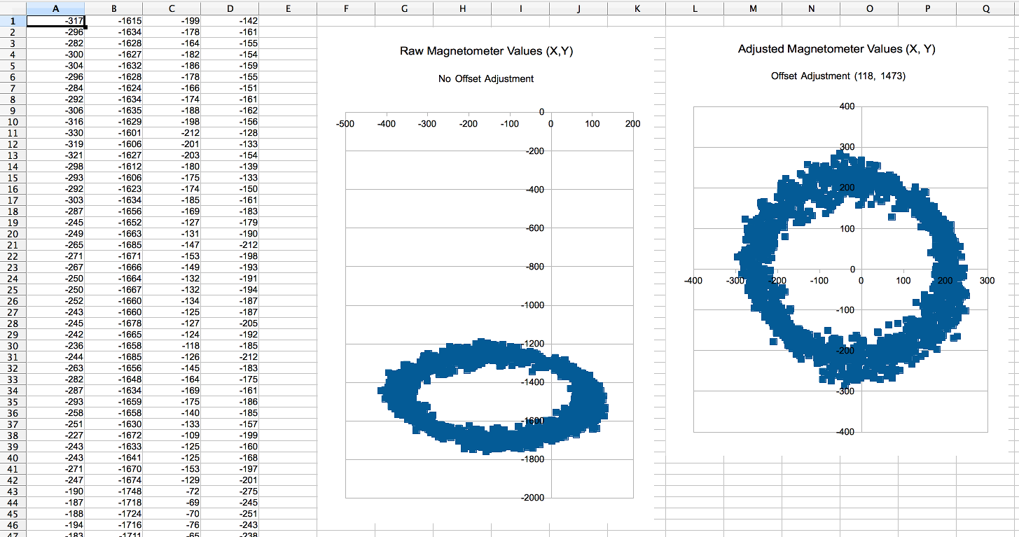
For the magnetometer, you have the option of entering a value manually (i.e. if you had obtained it via other experimental methods). The best option for most people, though, is to run the automatic calibration routine. Using this method, Stubby will slowly rotate in place, completing about four full rotations over the course of a minute or so. The raw magnetometer values (plus the adjusted values, using the current offsets) are streamed to the console. When the calibration is finished, the program computes the average for both X and Y, and asks if you want to set this as the new value:
Current offsets: 118, 1473
New (auto calculated) offsets: 143, 1483
Do you want to use these new offsets? (Y/N)
You can use the streamed raw / adjusted values to graph an X,Y scatterplot in your favourite spreadsheet program:
![]()
Whenever you are finished any calibration, back out to the main menu and select "Save" to persist the calibration values to EEPROM. These values are then automatically loaded on startup.
This program has been tested on Debian Jessie using python 2.7.8, and on OSX using python 2.6.9, but in theory it should be compatible with most modern python versions and operating systems - I have not used any weird modules or syntax here. The only non-standard dependency is pyserial, which is readily available on all platforms. If anyone tries to run it on Windows, please let me know how it works (whether good, bad, or ugly).
Cheers
-
Magnetometer Working
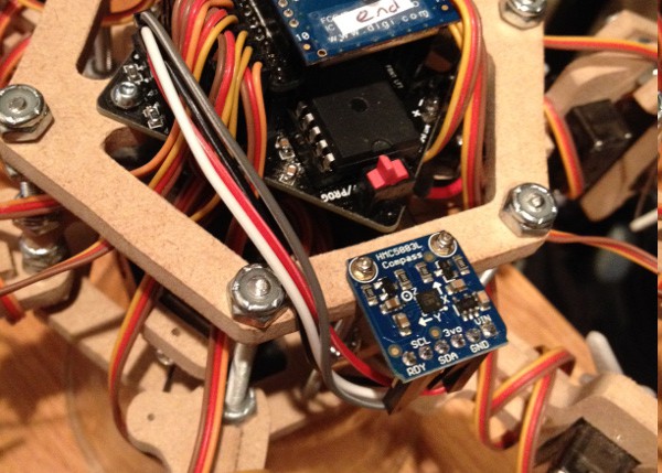
09/28/2014 at 05:28 • 0 commentsThe magnetometer arrived on Thursday (yay for Adafruit and their speedy shipping!); today I spent most of the day getting it working.
![]()
There were a few issues which I needed to overcome.
First, I had to read the raw values over i2c. This is easy enough; the only gotcha was that I didn't read the data sheet close enough, and I failed to notice that the axis are read in X, Z, Y order rather than X, Y, Z. (Really?! I wonder if there is a technical reason for this ordering, or what ).
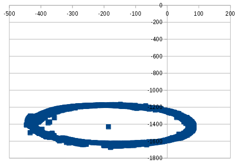
After I got the raw values, I used atan2 to convert the x,y co-ordinates into an angle (heading). The problem here was that (probably due to the magnetic fields of the servo motors) the Y axis was shifted very far down. This meant that all the angles were being read as negative. See a graph of the raw values below:
![]() By adding a constant offset to x and y, we got the readings to be properly centered around the origin.
By adding a constant offset to x and y, we got the readings to be properly centered around the origin.Next challenge was that I am operating in a magnetically noisy environment (there are 18 servos within centimeters of the magnetometer). Implementing a low pass filter against headings is actually much harder than you would think. (You have to remember the 'wrap around' at +/- PI). In the end, I apply a low pass filter on the raw x, y co-ordinates. A timer polls the magnetometer multiple times a second to ensure that the filtered heading is always accurate and up to date.
Finally, once I had accurate, filtered headings available at any time, I was able to implement a simple PID algorithm which compares the actual heading to the desired heading and makes any required corrections to keep the robot on course. This works very well: see for instance the video below, demonstrating the same programmed walk with and without using the magnetometer for course correction.
Some of my next steps include:
- Use the magnetometer when turning in place to ensure that we turn to the correct angle
- Add an auto calibration routine, which will be saved to EEPROM, so that we don't need to hard code the x,y offsets (which will likely be different for each robot anyway).
- Provide access to the raw magnetometer heading from the Processing API (corrected for mounting angle)
-
Third party build now working!
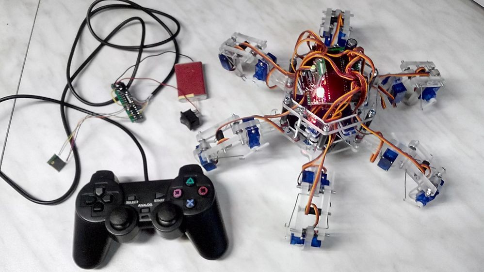
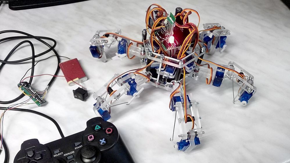
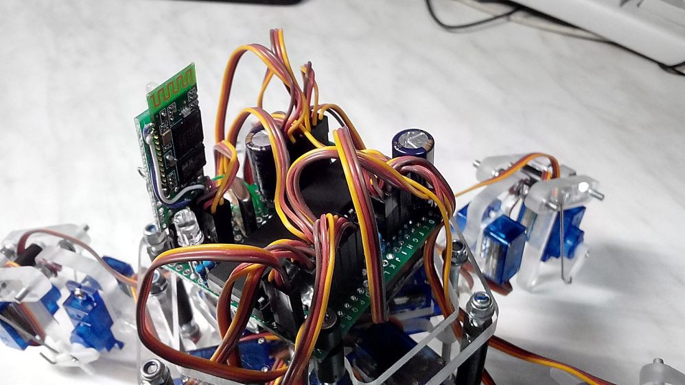
09/24/2014 at 21:12 • 0 commentsPetr H. has just finished his beautiful plexiglass Stubby build (at least enough to get it walking around). There is still a lot of cleanup and stuff to do, but everything seems to be working. To my knowledge, he is the first person to have completed their own version of Stubby (if someone else has completed their own version, I would love to hear about it).
He is controlling it with a Universal Controller, using two Bluetooth modules instead of XBees (a very good idea, as it keeps the cost down and allows for computer control without switching hardware).
His latest pictures are below, and he will hopefully be sharing a video in the not too distant future:
![]()
![]()
![]()
-
More Third Party Builds
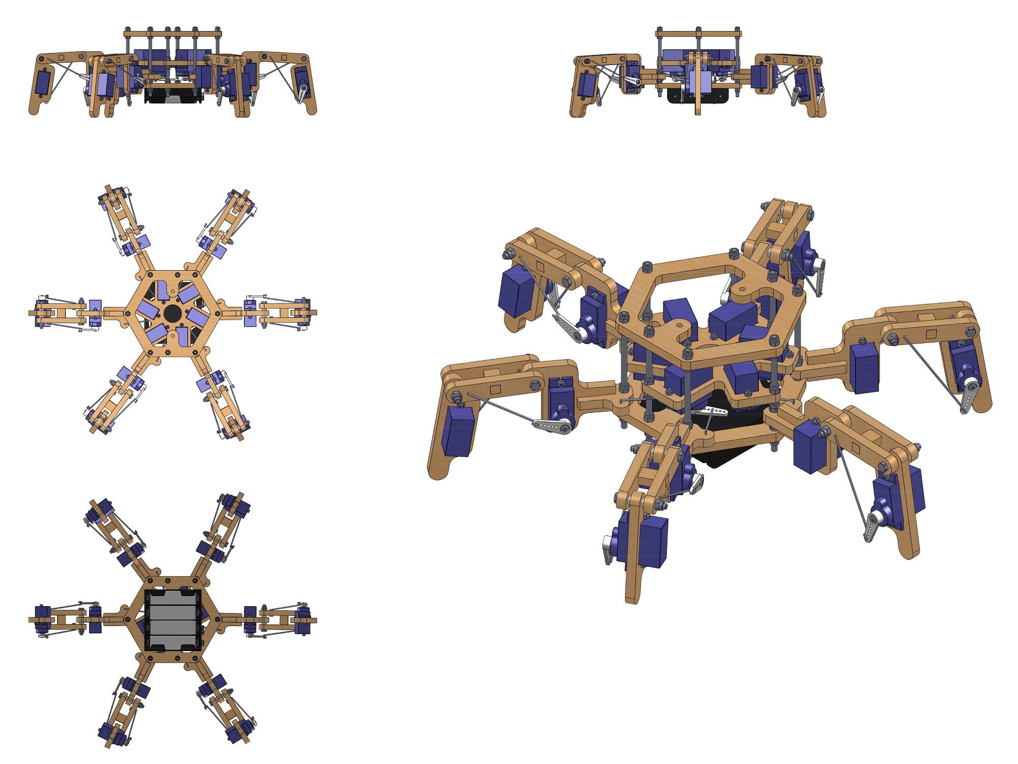
09/23/2014 at 22:37 • 0 commentsStanisław K is also working on his own version of Stubby. He has plans to eventually scale up the size to support larger servos, but initially he has converted all measurements to metric (my version has the CAD drawings in metric, but it uses imperial for drill sizes due to USA / Canadian screw sizes, #6, #4, etc).
Prior to actually making it, he has modelled the entire system in SolidWorks 2013. An example of this modelling is below:
![]()
Some other (very high resolution) plans he has created include: 3D body view, body component listing, exploded body view, and leg assembly (part 1 and part 2).
In case anyone else has the source SolidWorks files, he has graciously sent me everything that he has. You can download this for yourself and play as you see fit (warning: this is a 130MB archive file, and may take some time to download).
-
Two more Stubby builds, well underway
09/21/2014 at 18:49 • 0 commentsOver the past couple of days I have received photos from some hackers building their own versions of Stubby.
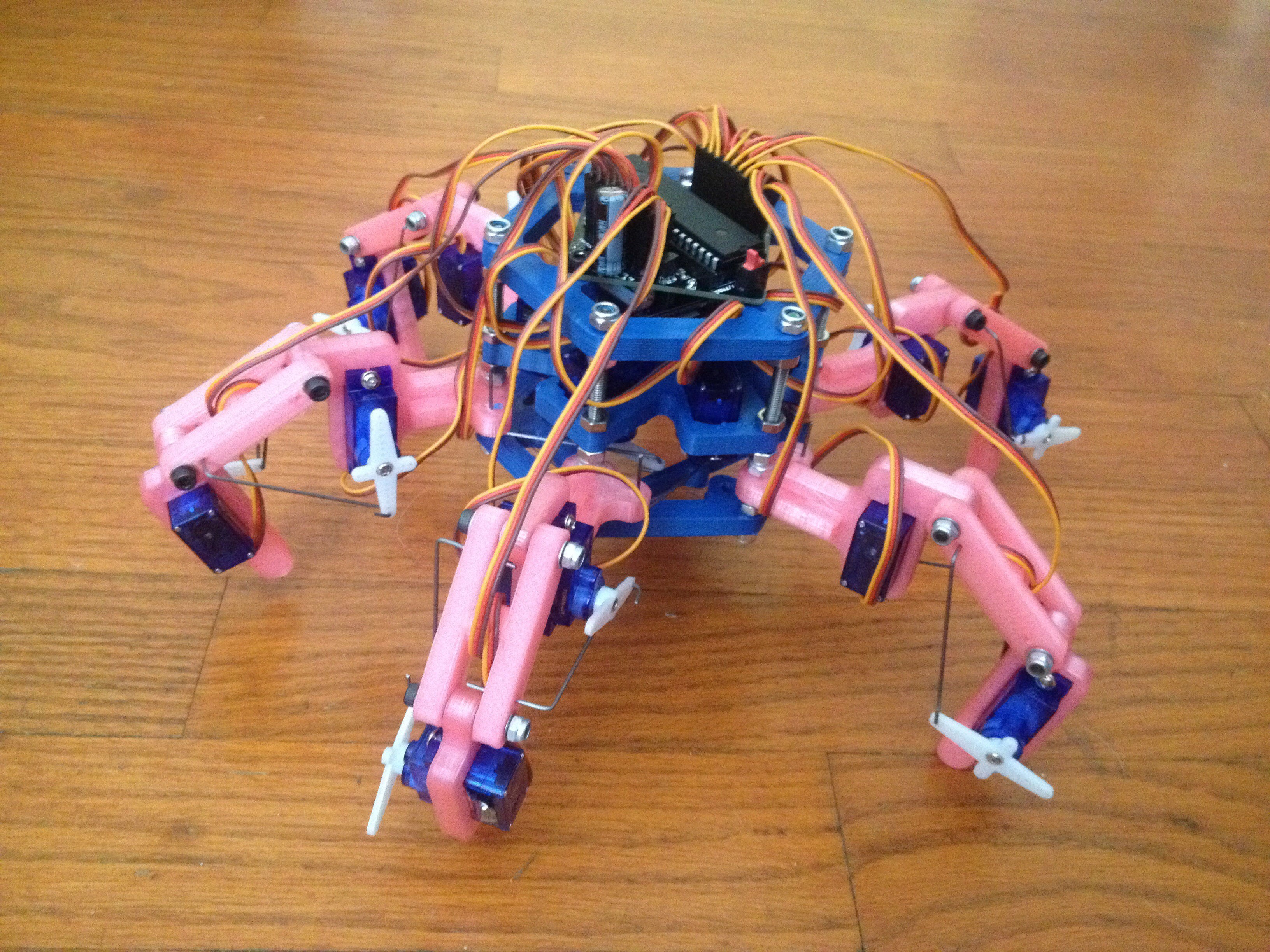
First off, David S has been working on his version for a while. He has 3D printed a frame in a very attractive pink and blue (which IMHO looks great with the blue servos). He is now getting the calibration all worked out, and hopefully this Stubby will take its first steps within the week:
![]()
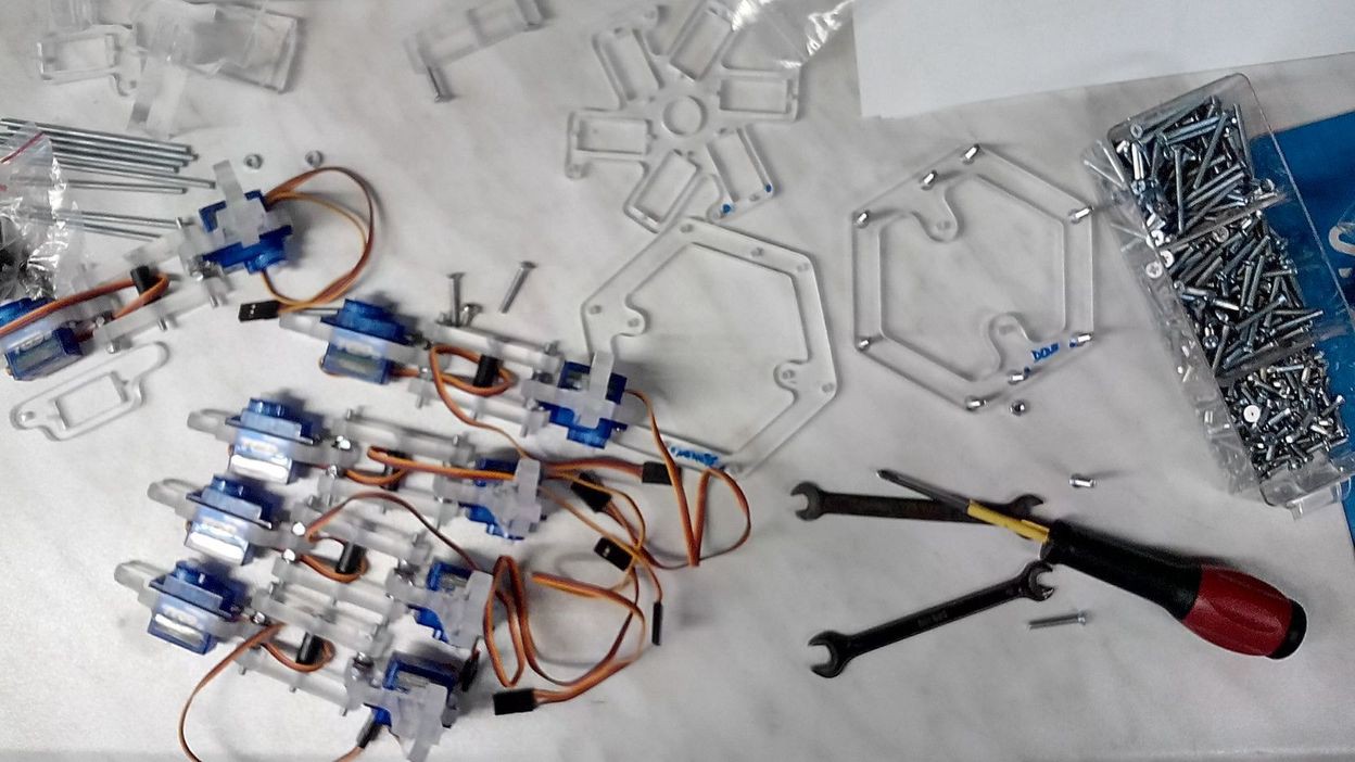
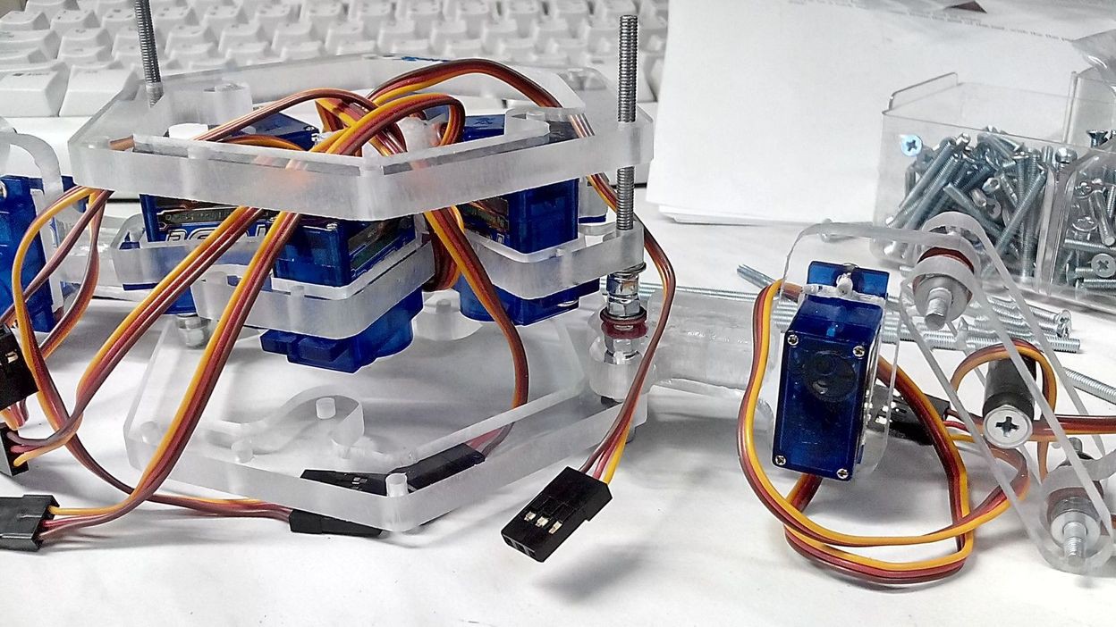
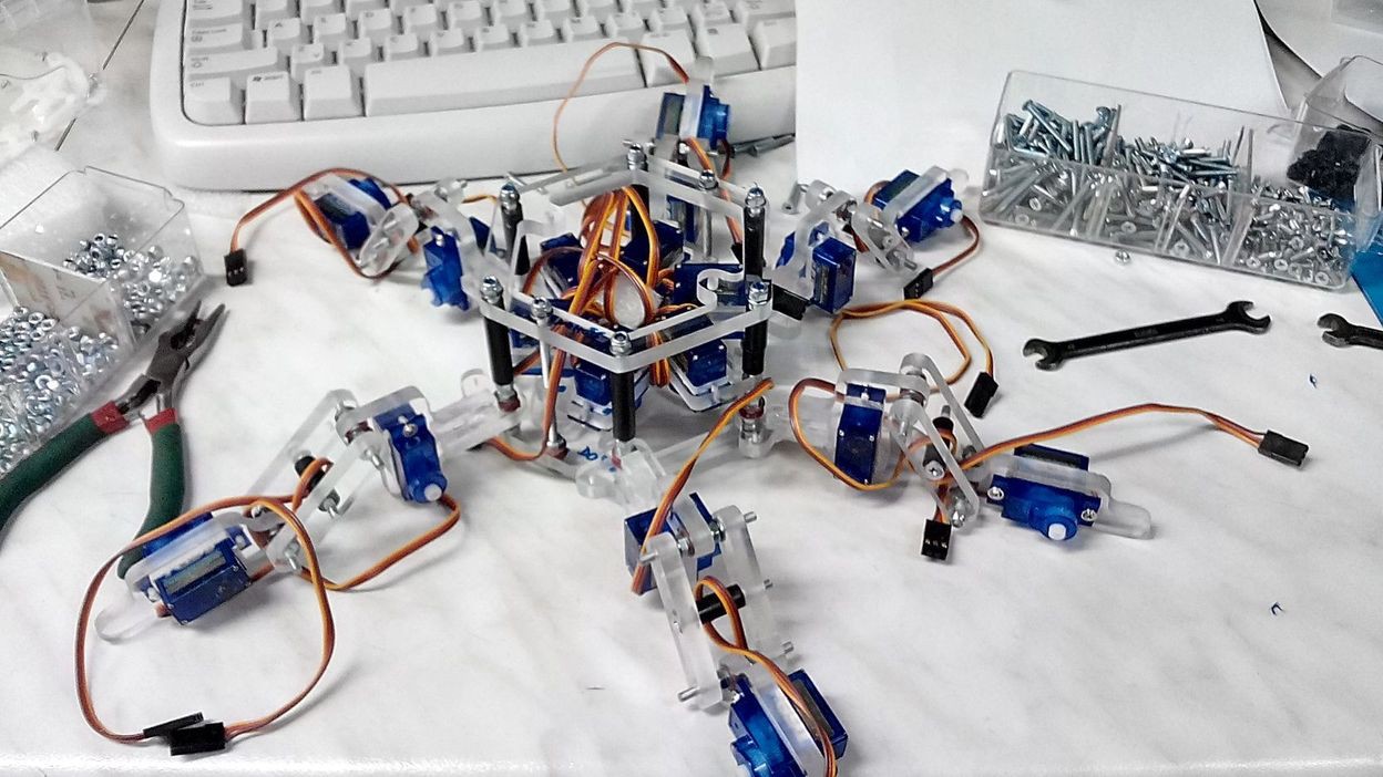
Also, we had shown off Petr H's beautiful clear plexiglass frame a week or so ago. He is now mostly done assembly, and ready for electronics + calibration. Some pictures of the assembly are below:
![]()
![]()
![]()
Cheers
-
Semifinals Requirement List
09/17/2014 at 18:39 • 0 commentsTo keep things easy for the judges, this post contains links to all the requirements of the Hackaday Prize Semifinals. It will be updated as progress is made, up to the deadline (Sept. 28).
- Video: Princess Sparkle and I have been working on our semifinals video for the past week and a half, and we are now finally satisfied with it. Enjoy!
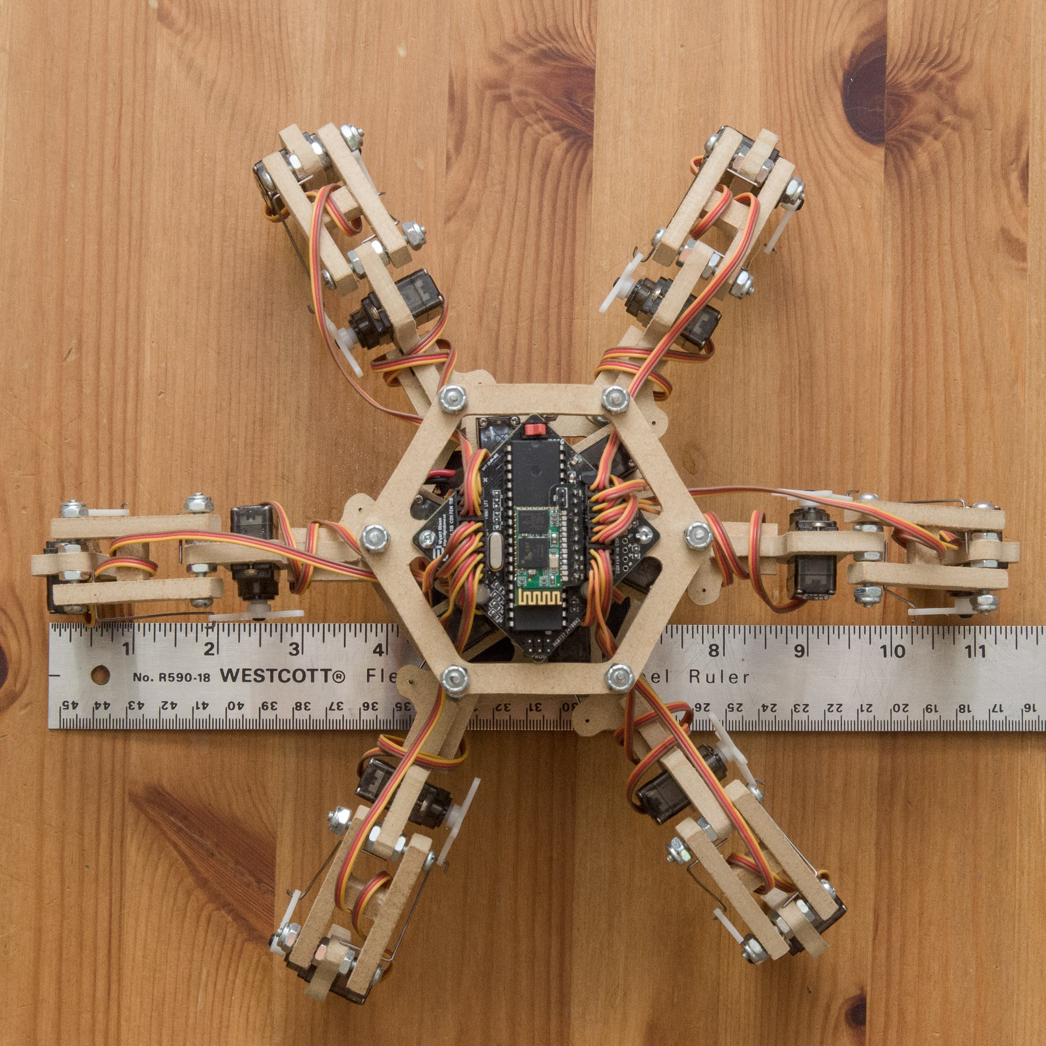
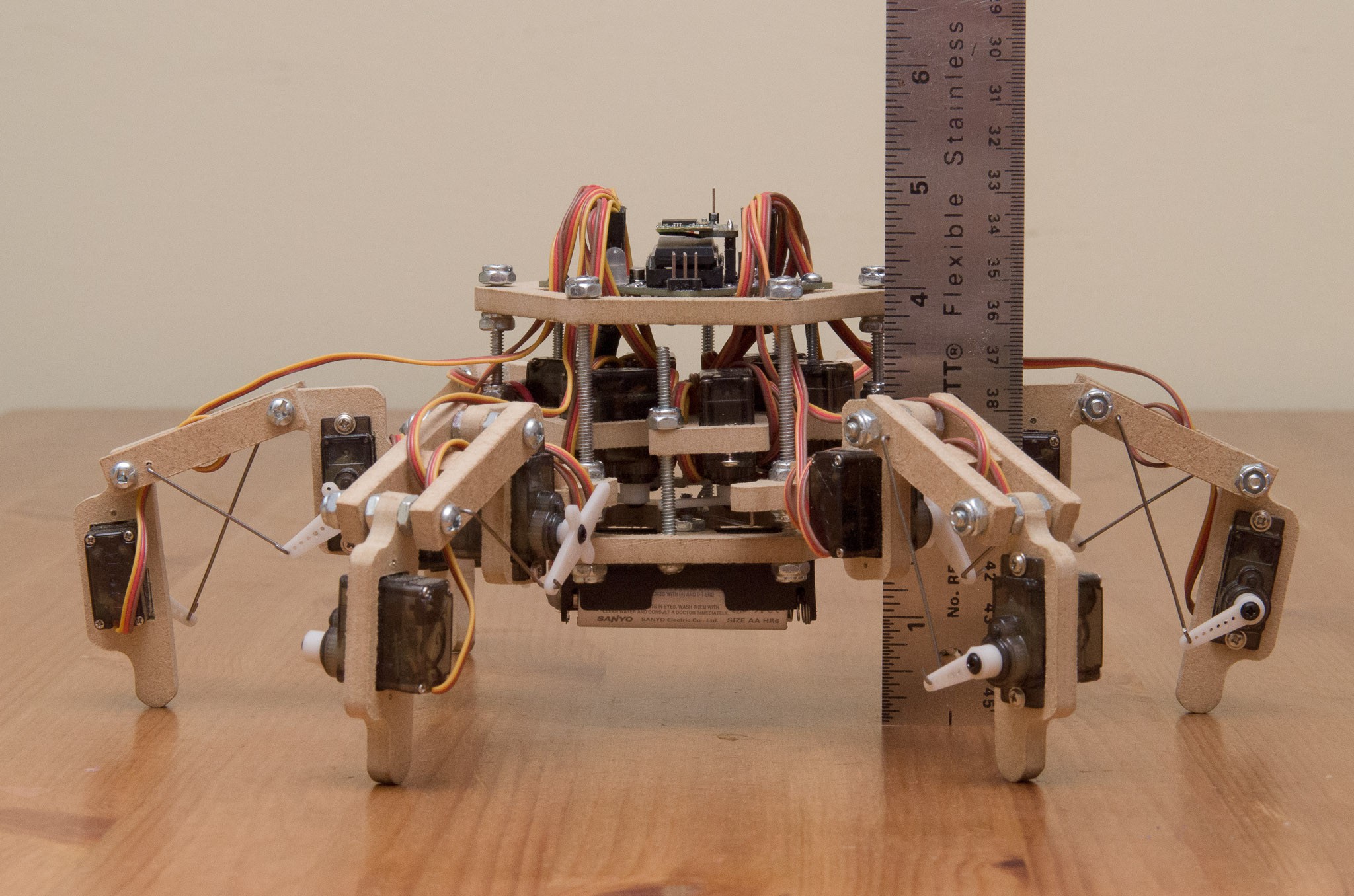
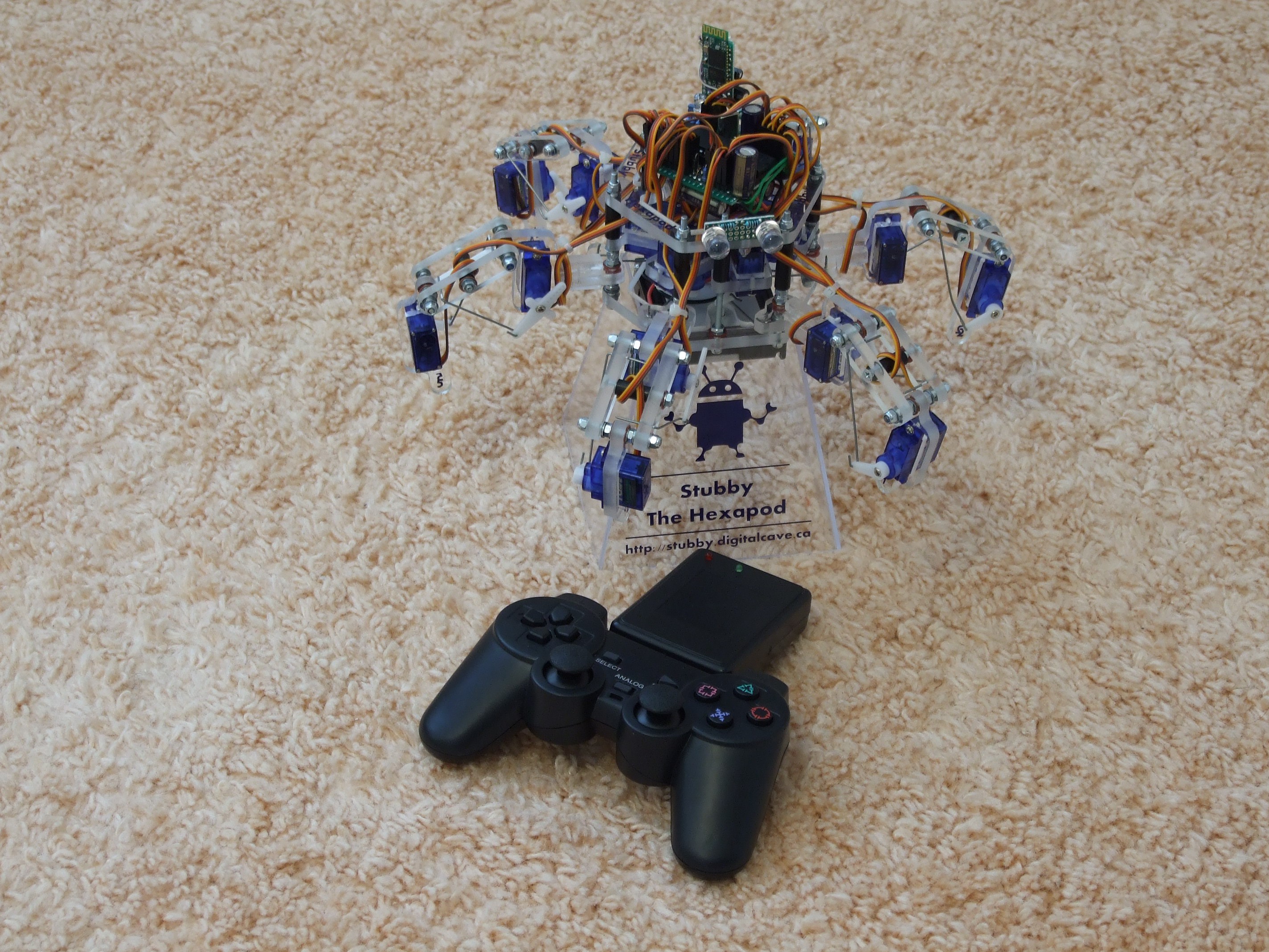
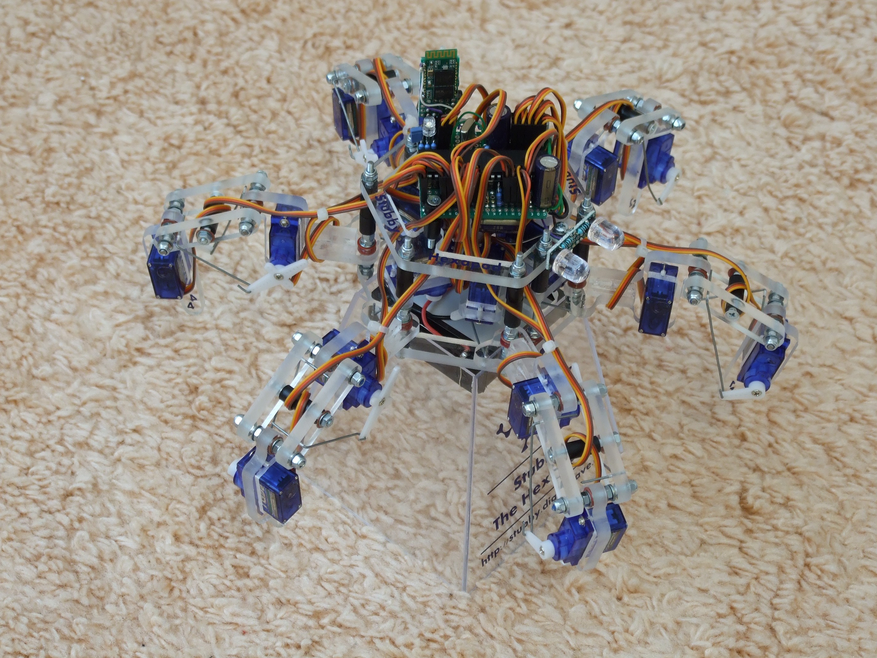
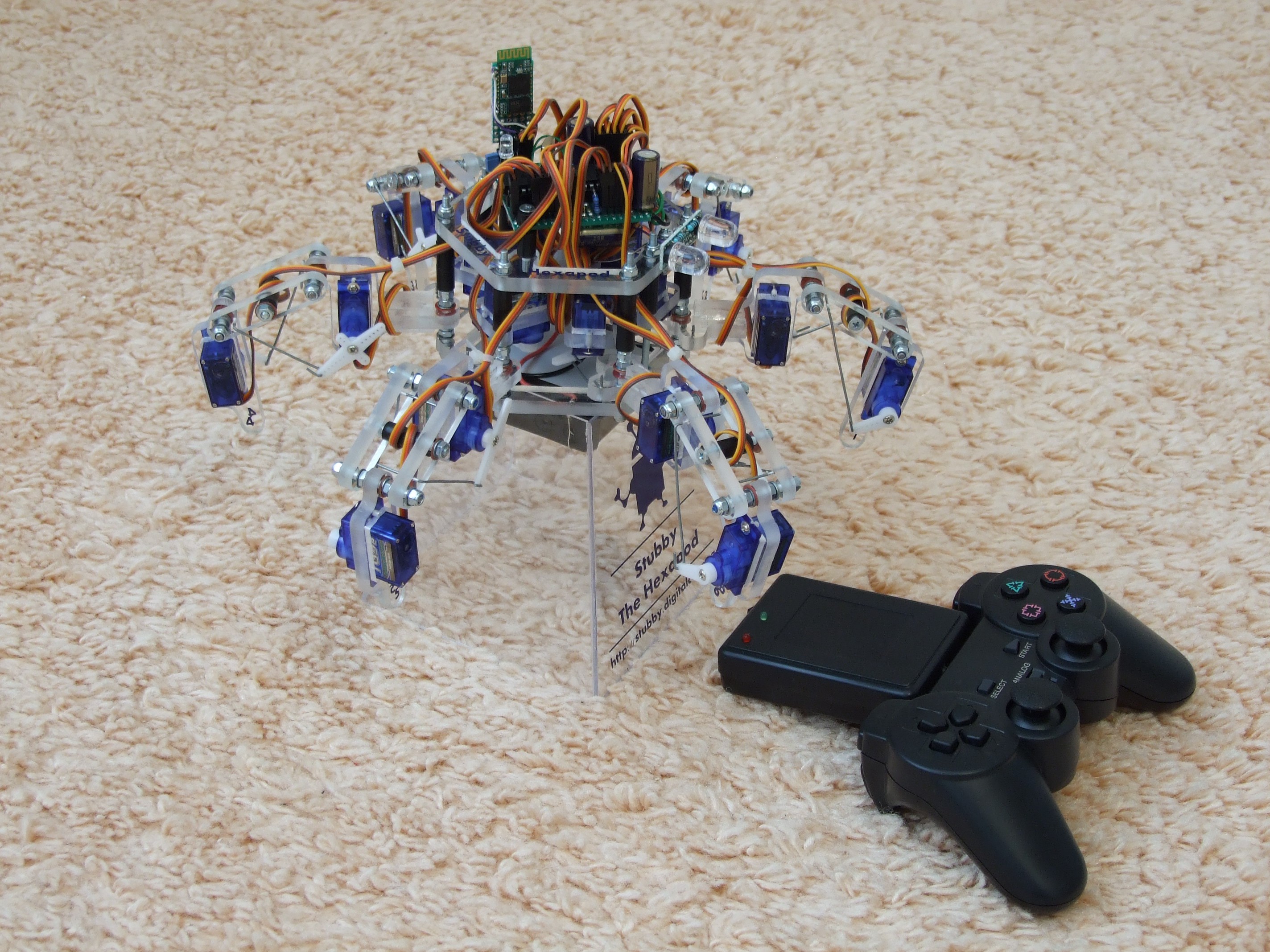
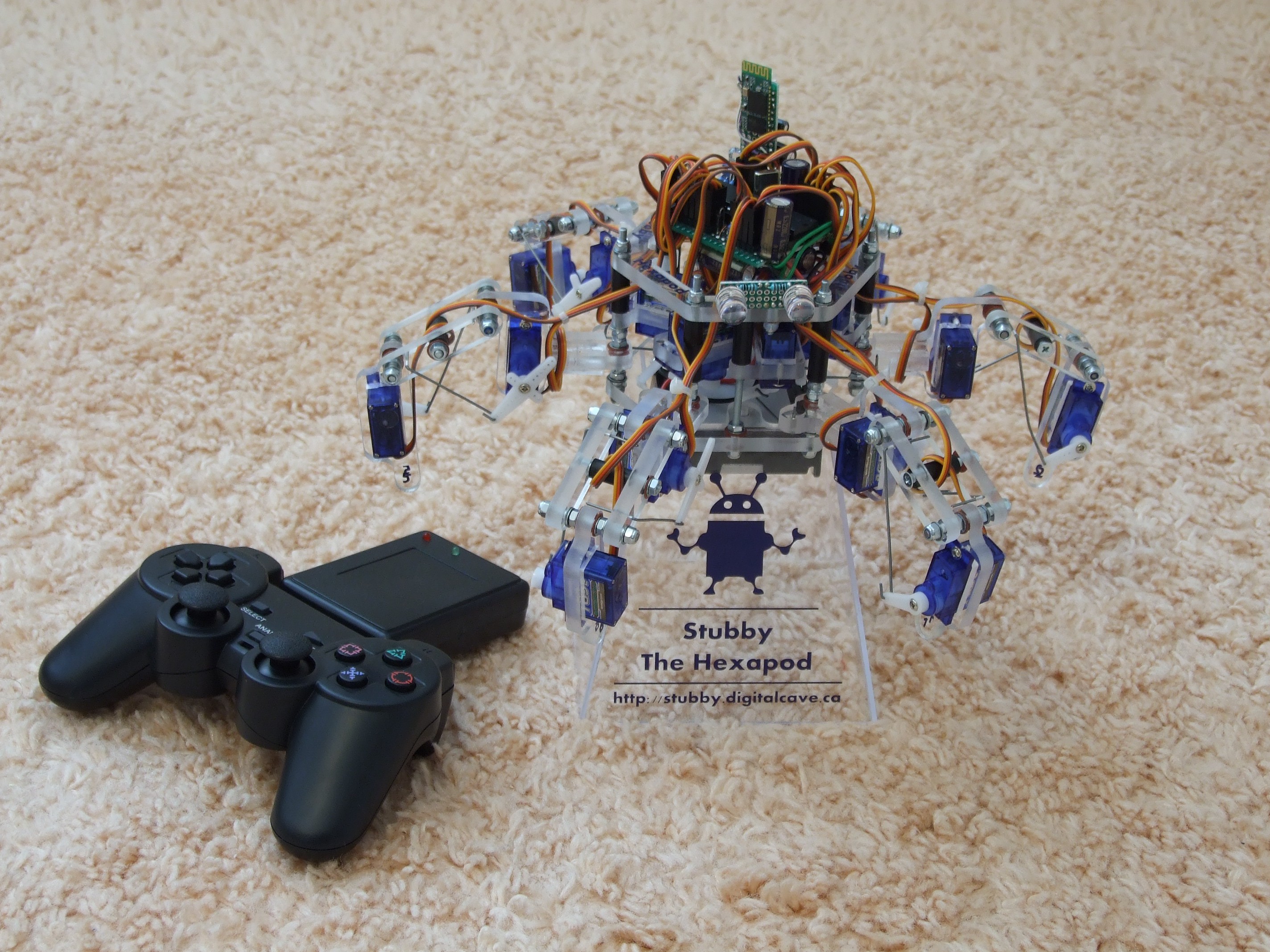
- Finished Product (Frame): The frame design of Stubby is finished; if one were to make a commercial product from these designs, it would most likely be laser cut plexiglass or similar instead of hand cut MDF, but the shape and dimensions would be identical. As indicated by Mike, since the design is finalized, it is fine to show a picture rather than an artistic rendition. (The only physical changes remaining are minor ones: an updated PCB with surface mount components, and a slightly different layout for the top body layer to accept the new PCB, which has mounting holes in different locations). Below are top and side views of the robot, with a ruler for scale:
![]()
![]()
- Finished Product (Electronics): The board you see in all the pictures and videos is the Revision 1.0 board. This board uses through hole and large SMD components, and is solderable by hand. There are newer versions of this board (rev 2.0 and 2.1) which use smaller SMD components; 2.1 even has an on-board magnetometer, so that you don't need to buy a standalone board. A commercialized version of Stubby would utilize the rev 2.1 board, which has been designed to be easily manufacturable (no components on the back, ready for pick and place machines, etc).
- Connectedness: Stubby is designed to be link agnostic. Any serial connection can be used for control. I personally have used HC-06 Bluetooth modules and XBee radios. Revision 2.x of the board includes a standardized 6 pin header with the FTDI cable pinout (which would allow users to plug in directly using a USB serial cable for testing), along with breakaway adaptor boards which allow the XBee / HC-06 boards to plug in directly. The rev 2.x boards allow users to configure the serial module to run at either 5v or 3.3v for the ultimate level of compatibility with existing hardware.
- System Design Documents: There are a few of these. The Frame Plans are printable plans which can be glued to a piece of MDF and cut with a scroll saw (PDF, DXF). The System Communication document describes how the Processing library and the Universal Controller both talk to Stubby, and describes the protocol and the most common command messages. The Electrical Schematics (revision 1.0) and Board Layout describe the circuit as currently implemented (KiCad, Gerber). (The revision 2.0 boards have been ordered but have not yet arrived and so are untested; if you are interested, you can see the schematic, board layout, and gerbers for this version too. Functionally it is very similar; the differences are a new power supply to allow the 5v ultrasonic rangefinder to work, more capacitors for filtering the large power drops encountered when running 18 servos, and many more surface mount components). Build instructions and components lists are available on the Hackaday.io page as well as (more legibly formatted versions) on my web site.
- Licensing: The entire Stubby design (including the frame design, schematics, board layout, software, Processing library, etc) is released under a Creative Commons Attribution Share-Alike license. The source for life, the universe, and everything (at least everything which is related to Stubby) can be found by browsing or cloning my git repository. (On a somewhat related note, all software used for the design, manufacture, and programming of Stubby is also open source and cross platform. This includes the Processing framework, KiCad, QCad, avr-gcc + avrdude, git, ant, etc).
- Innovation: To my knowledge, Stubby is the least expensive (~$150 at quantity 1) and easiest to manufacture (no laser cutter, 3D printer, or CNC required) hexapod with 3 degrees of freedom per leg. To keep costs down, I used cheap micro servos rather than the more expensive robotics servos. With a traditional hexapod design, the servos are directly connected to each leg segment. This requires a lot of torque to move the leg segments, and would not be possible when using micro servos. By using push rods, I trade movement range for torque, allowing the use of cheap servos. In addition to the servos, I have kept the cost of electronics to a minimum by driving everything with a single cheap microcontroller (other projects tend to use dedicated servo control boards). A hand written PWM library (including assembly code for the time-sensitive ISR) allows this microcontroller (running at only 12MHz!) to control all the servos while, at the same time, performing complex trigonometric calculations in real time. Keeping costs to a minimum is very important for my Hackaday Prize goal of teaching children programming, as that is likely to be much closer to an educational institution's (or a family's) budget than a traditional hexapod design would be.
- Reproducibility: There are a number of hackers worldwide who are currently working on their own versions of Stubby. Some have already finished, others are well underway. I have many project log updates which detail the progress of these third parties.
- User Experience / Interface: The Processing API is central to this project. I am making an effort to keep this as simple as possible, while still retaining the features needed for exploring procedural and event driven programming. While today the Stubby library is installed manually, once it is closer to completion I will submit it to the browsable list of libraries available directly from the Processing API. Furthermore, with Stubby's flexibility in communication, it can also be controlled by hand using a Universal Controller (which in my case is just a hacked PS2 controller, but could be pretty much anything that sends the proper messages over the serial port). When using the Universal Controller, I use the same control techniques that are used in video games (e.g. movement, strafe / sidestep, turning, etc). If you pass the controls to pretty much anyone between the ages of 4 and 60 they have no problem figuring out how it works within seconds.
-
Adding a Magnetometer
09/16/2014 at 05:03 • 0 commentsWhile working on the Processing API with Princess Sparkle, we found that Stubby was having problems going perfectly straight; it would veer one direction or another, depending on the angle of movement. After hours of research, we determined that the problem was due to slight variances in each leg. When walking, these tiny differences in each step compound, and make for large errors in the outcome. (This is the same principle which happens in a flock of female velociraptors with spliced frog DNA, where some individuals will spontaneously change gender... oh wait, nevermind.) More accurate calibration of the legs can help, but it doesn't eliminate the problem completely. Compounding this problem, there are also inaccuracies when turning in place, depending on the surface that the robot is walking on (e.g. tile vs. carpet).
Warren and I discussed a number of options on how to solve this. The idea which seems most promising (both due to the simplicity, the low cost, and the low processing requirements) is to add a magnetometer. This will allow Stubby to keep track of the direction it is facing; when moving, we will use the feedback from this sensor to make small course adjustments as the robot is walking (basic PID functionality, although the I component will probably not be included, and D, if any, will be minor). The biggest unknown at this time is whether the magnetometer will a) be accurate enough and b) will work properly even though it is encircled by (admittedly small) motors.
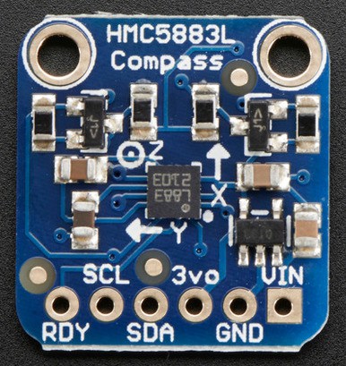
Since I have just ordered the rev 2.0 PCBs (which, BTW, are marked as Shipped, yay!), I bought a standalone i2c magnetometer from Adafruit for prototyping:
![]()
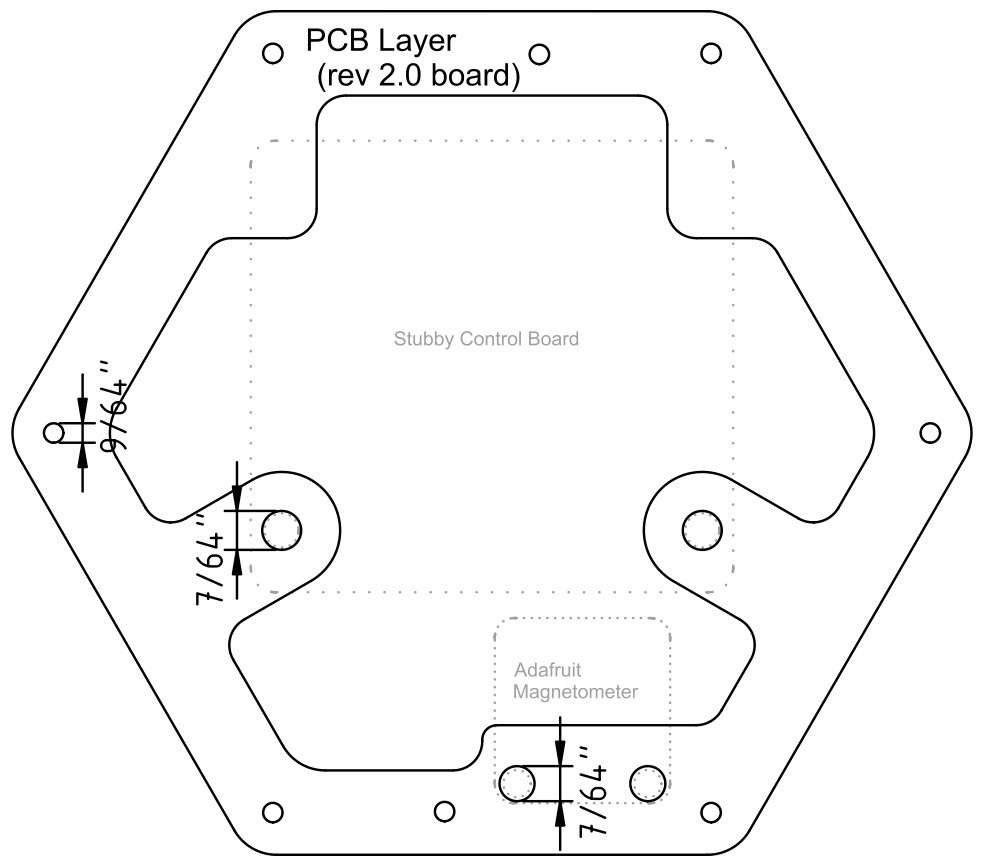
Assuming we can get things working as planned, I will add this chip to the Stubby control PCB itself. In the mean time, I have a new top layer designed, which fits the new control PCB and has room for the magnetometer as well:
![]()
Cheers
-
3D Printed Frame + .STL Bugfix
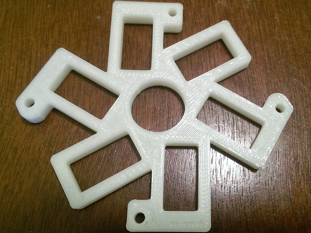
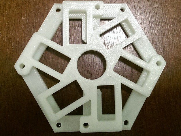
09/15/2014 at 13:45 • 0 commentsEllison, a hacker who is working on a 3D printed version of Stubby, emailed me yesterday to share his progress and to inform me that there was a bug in the previously uploaded servo layer of the .stl files - two of the screw mounting holes did not line up with the other layers. He has graciously provided an updated file, and has permitted me to share the pictures he sent.
I have added the updated .stl file to the 3D printer source files (I have kept Joshua Thomson's original design as well; the updated one is called Servo layer - Alternate.stl. Anyone who prints their version should verify which one makes sense for them.)
Ellison's version of the servo layer, along with a photo showing the alignment between it and bottom layers, can be seen below:
![]()
![]()
Stubby the (Teaching) Hexapod
100% open source robot platform with accessability and affordability in mind: teaching children of all ages about robots & programming


 By adding a constant offset to x and y, we got the readings to be properly centered around the origin.