The Big One
-
Processing Library Download and Instructions
09/13/2014 at 22:55 • 0 commentsFor those who want to try controlling Stubby from the computer in Processing, I have attached the current build of the Processing library. All planned features are not yet completed, but it is a good start, and is plenty to verify connectivity; Princess Sparkle is having a blast playing with the different options.
You can download the library from my web site. Once downloaded, unzip it to the Processing libraries folder, within the Sketchbook. (By default this is C:\My Documents\Processing on Windows, and ~/Documents/Processing on the Mac). Within the sketchbook folder there should be one called "libraries". Unzip stubby.zip to that location; you should see a folder structure similar to this:
<sketchbook>/libraries/stubby.zip
<sketchbook>/libraries/stubby (folder)
<sketchbook>/libraries/stubby/library (folder)
<sketchbook>/libraries/stubby/library/stubby.jar
<sketchbook>/libraries/stubby/library.properties
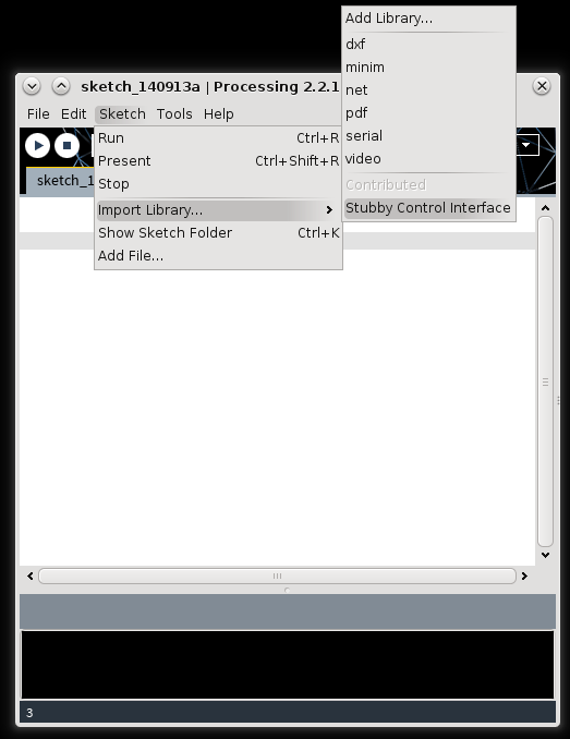
Restart Processing, and you should see the Stubby Control Interface library in the Libraries list:
![]()
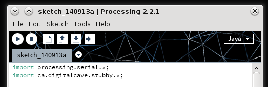
Go ahead and add it to your sketch, along with the Serial library:
![]()
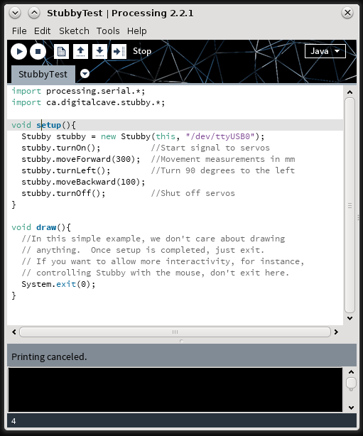
A basic program can include all commands in the setup() method, and can exit as soon as Setup is completed:
![]()
All currently supported commands are listed below. More are coming soon; you can always get the latest release of this library by downloading the Git repository, navigating to 'projects/stubby/processing', and typing 'ant' to build the library.
/**
* Turn the servos on
*/
public boolean turnOn();


/**
* Turn the servos off
*/
public boolean turnOff();


/**
* Move the specified distance in the indicated direction at the given speed
*
* @param linearAngle Angle to move.  0 is straight forward, negative angles are right, and positive angles are left.  Angle in degrees.
* @param rotationalAngle Rotational angle to turn.  Measured the same as linear angle.
* @param linearVelocity Speed to move; unsigned 8 bit integer value between 255 (fastest) and 0 (slowest).
* @param rotationalVelocity Speed to turn; same range as linearVelocity.
* @param distance Distance to move (in mm).
* @return
*/
public boolean move(int linearAngle, int rotationalAngle, int linearVelocity, int rotationalVelocity, int distance);


/**
* Convenience method to walk in the specified direction for the specified distance.  See above for parameter descriptions.
*/
public boolean move(int linearAngle, int distance);


/**
* Convenience method to walk forward.
*/
public boolean moveForward(int distance);


/**
* Convenience method to walk backward.
*/
public boolean moveBackward(int distance);


/**
* Convenience method to walk right.
*/
public boolean moveRight(int distance);


/**
* Convenience method to walk left.
*/
public boolean moveLeft(int distance);


/**
* Rotates to the specified angle.  Positive values rotate clockwise, negative rotate counter clockwise.
* @param angle In degrees, with 0 being the direction the robot is currently facing.  Negative angles are to the right (clockwise), positive to the right (counter clockwise)
* @param rotationalVelocity Speed to turn, between 0 and 255
*/
public boolean turn(int angle, int rotationalVelocity);


/**
* Convenience method to turn right
*/
public boolean turnRight();


/**
* Convenience method to turn left
*/
public boolean turnLeft();


/**
* Convenience method to turn around 180 degrees (counter clockwise)
*/
public boolean turnAround();


/**
* Convenience method to turn around 180 degrees (clockwise)
*/
public boolean turnAroundClockwise();
Cheers
-
Another Hacker's Stubby Build
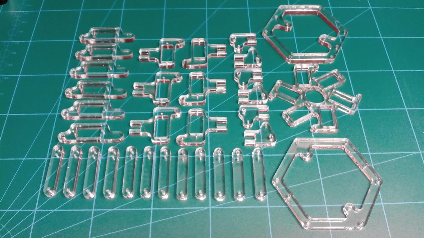
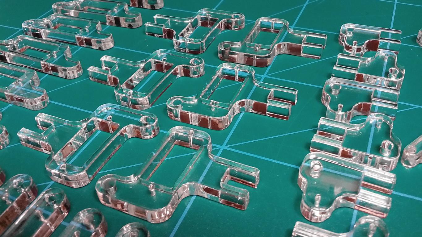
09/11/2014 at 20:57 • 0 commentsI just got an email from Petr H. today, another hacker who is building a version of Stubby. He has chosen to go the route of laser cut plexiglass, and wow, does that ever look snazzy! He has provided me with some photos of the parts, and has graciously given me permission to post them here:
![]()
![]()
He is still waiting for the servos to arrive, but I am eagerly awaiting how the final build will look!
Cheers
-
AVR-GCC Compiler Issues
09/10/2014 at 22:39 • 0 commentsA few days ago I received an email from someone who is building their own version of Stubby. He reported that my code didn't compile. The error he was getting was a very strange one, including a bunch of lines with things like this:
/usr/lib/gcc/avr/4.7.2/../../../avr/lib/avr51/libm.a(atan2.o):../../../libm/fplib/atan2.S:140: relocation truncated to fit: R_AVR_13_PCREL against symbol `__addsf3'
defined in .text section in /usr/lib/gcc/avr/4.7.2/avr51/libgcc.a(_addsub_sf.o)
I found some sites which suggested adding -lm to the command to work around a bug in AVR-GCC 4.7, but that didn't work either.
In the end, he upgraded to AVR-GCC 4.8.1 (the same version which I am using), and it compiled fine. I am still not sure what caused the errors, but whatever it is, it works on the latest versions. So, if you are trying to compile Stubby code, and are getting errors like this, try upgrading your compiler.
Cheers
-
First Steps (via Processing API)
09/09/2014 at 03:47 • 0 commentsTonight Stubby took its first steps via the Processing API over Bluetooth. The Processing test program is very simple:
Stubby stubby = new Stubby(this, "/dev/rfcomm0");
stubby.turnOn();
stubby.moveForward(200);
stubby.moveBackward(200);
stubby.turnOff();
Within the library's API, each command handles the protocol communication, including acknowledges and command complete messages. For instance, when the Processing program calls stubby.turnOn(), behind the scenes the API sends message 0x20 (power on), and waits for message 0x01 (acknowledge) from the robot before returning. The move commands require two acknowledgements before returning: first, the command ack, then the command complete message.
The biggest hurdle tonight was actually getting Bluetooth set up on Debian... sigh. It seemed really simple at first; the driver seems to be built into my kernel, and even getting the device paired (via KDE's Bluetooth GUI) is quite easy. Actually getting the serial port created is a headache, though, and resulted in complete system lockup a couple of times, requiring a hard reboot (something I have not had to do in Linux for years).
Currently I am manually setting the serial port up, doing the following steps:
$ hcitool scan
Scanning ...
        00:12:02:01:01:97       Stubby

$ sudo rfcomm bind rfcomm0 00:12:02:01:01:97
Eventually I may put this in an init script, but for now I am not confident enough in the procedure to want that. I tried putting this information into /etc/bluetooth/rfcomm.conf to get it to automatically bind, as various tutorials suggested, but that didn't appear to work. More investigation is definitely required, but it is too late for me tonight.
In short, I still don't know if I am doing it right... if anyone has experience with this please let me know.
Edit: Well, it looks like it may be just problems with Debian Testing. I downgraded the bluetooth packages to the Debian Stable versions and they appear to be working a bit better so far. Here's to hoping...
Edit 2: Nope, no such luck... whatever the problem is, it appears to be at the kernel / driver level; either the driver does not properly support SPP, or something else is seriously wrong with the Bluetooth stack. When using it, it works sometimes, but a good 25% of the time when I try to connect it causes a kernel panic and I have to do a hard boot (and sometimes even a hard boot is not sufficient, and I need an actual cold boot). I am going to return that Bluetooth adaptor and try to figure out alternatives, possibly even just throwing an XBee on the end of an FTDI cable. Boo-urns! :-(
On the bright side, though, Princess Sparkle's laptop, which has Bluetooth built in, works perfectly fine. I will use XBee when debugging on my desktop, but she can still use Bluetooth when making her own programs.
-
Revision 2 Boards Ordered
09/05/2014 at 02:46 • 0 commentsI have just placed the order for the revision 2 boards. Here's to hoping I worked all the bugs out of it... I have not previously used this particular step-up regulator (NCP1400A), nor have I made any board which is quite as tight as this one. Oh well, I can always green-wire the thing if needed. (One 'bug' is that I did order the wrong color, though... I normally order black PCBs, but my stupid mis-clicks made it blue this time, and it was already submitted to the fab house via DirtyPCBs before I could get it changed. Oh well, at least it will match the blue rangefinder!)
If anyone wants to order a batch of their own, you can now use the DirtyPCBs store link. (Once they arrive, I will likely have a few spares for sale to people in Canada / USA... anywhere other than that, and it makes more sense to just order from Dirty directly, as the shipping for me costs more than 10 copies of the board shipped from China).
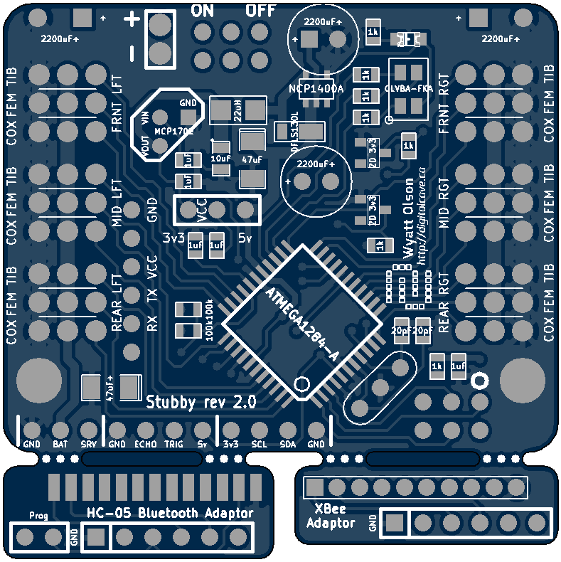
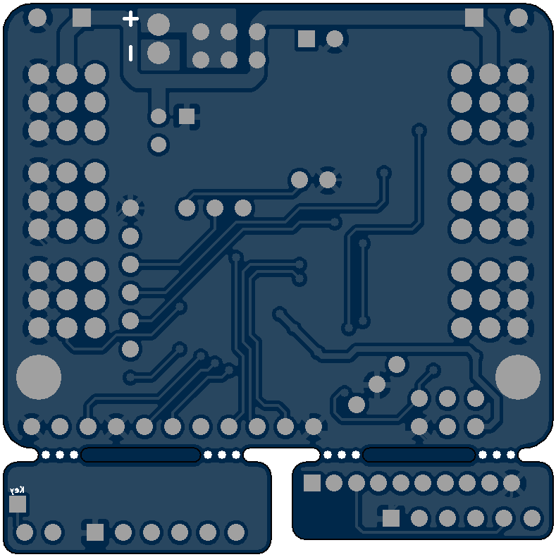
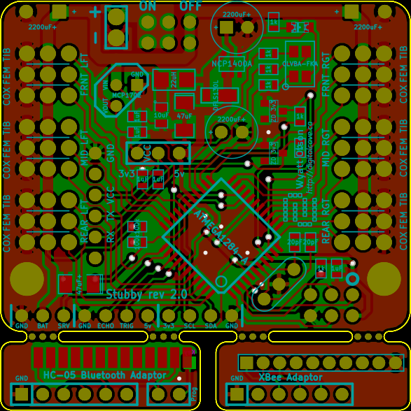
The actual rendering of the board is below. It is almost identical to the one posted a few days ago, except that I adjusted the breakout boards a bit to make the XBee / Bluetooth adaptor fit better in between the various components.
![]()
![]()
-
Protocol Changes Implemented
09/03/2014 at 02:51 • 0 commentsThis evening I have finished implementing the changes to the Universal Controller / Stubby protocol; I changed from using a single byte per message to using a multi-byte framed packet per message. This allows me to send more complicated information (such as strings, debug messages, double values, etc) and also gives me the flexibility to have more commands defined (which is essential for the planned Processing API additions).
As of now, Stubby can talk to the Universal Controller using the new protocol, and can do everything that it was previously able to do (walk, rotate, body translation X/Y/Z, body rotation X/Y/Z). Next step is to add support for the Processing API; however since both pieces are now speaking the same language, it is pretty easy to add a few more conditionals to the message dispatching function.
For other projects looking for a simple, multi byte framed protocol, take a look at the library in lib/avr/protocol - this includes documentation of the protocol as well as a C implementation (for AVR, but trivially ported to other platforms or even languages). Using the library on an AVR is easy; implement a few functions, as defined in the protocol.h file, and watch the messages as they come into the dispatch function. For an even easier implementation, if you are using my serial library, you can just substitute serial_async_rx.c for protocol_serial.c in your Makefile.
Cheers
-
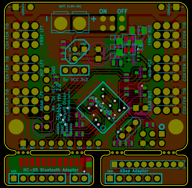
Revision 2 PCB Design (Final?)
09/01/2014 at 22:42 • 0 commentsI spent a few more hours on the new rev2 design in KiCad. Previously, I had components on the front and the back; I was now able to move all components to the front. (This will make a difference in manufacturing... if you get boards pre-populated from China, apparently it is quite a bit easier (read: cheaper) to have all the components on the same side. Furthermore, it should make things easier for me as well: since I am using a heat gun for reflow soldering, if I had components on the front and the back I would need to do two separate reflows, which would increase the risk of moving components previously soldered or even over-heating components.
I am going to give myself a bit of time to mull over this board, and if there is nothing which I realize needs to be changed, I will submit my order within a week or so.
The latest rev2 board design is below:
![]()
To recap from the last log update, I felt the need to change the PCB design from rev1 to address a few shortcomings of the previous board:
- 5v boost regulator (input from a heavily filtered the 3.3v linear regulator) will allow for 20MHz operation (vs. 12 MHz operation in rev1), as well as allowing for 5v peripherals (most notably the ultrasonic range finders)
- Provide explicit pins for the rangefinder plus an extra servo to let the robot 'look' up and down (tilt the rangefinder)
- Breakaway adaptors for both XBee and Bluetooth radios, so there is no need to buy the Sparkfun XBee adaptor
- A more standard pinout for the serial connection: rather than using the 10 pin XBee connection (adapted from 2mm to 100mil spacing), I now use the 6 pin FTDI pinout (and include a jumper to configure whether the serial port is powered at 5v or 3.3v). This saves some board space, and would simplify debugging as I can simply plug in a cable rather than messing about with RF modules.
- A bit of space between each leg's servo connectors (they all fit on the rev1 board, but it gets tight)
- Board space for additional capacitors on both servo power supply rails as well as the 5v and 3.3v rails (vs. nothing on rev1, and haphazardly placed components on the semi-official rev1.1)
The main disadvantage is that it is a lot harder to solder (reflow soldering is pretty much a requirement for this board, which unfortunately moves it out of the entry-hobbyist range).
(For those who have made their own robots using a rev1 board, no need to worry... I plan to keep support in the codebase for rev1 for the foreseeable future. The main advantages of rev2 are in relation to Bluetooth / computer control, for my Hackaday Prize project. If you are controlling Stubby by hand using the Universal Controller, rev1 does everything that rev2 will do).
-
Serial Protocol Design
08/29/2014 at 15:48 • 0 commentsBelow is the initial design document for the serial protocol (see protocol.txt for the latest version, as this will likely change over time).
Protocol Info
Message Structure (bi-directional):
Segment Length Frame Start 1 byte (0x7e) Length 1 byte Command 1 byte Payload 0 - 254 bytes Checksum 1 byte Commands:
There are four logical message types:
- 1) PC initiates a message to Stubby
- 2) Stubby responds to a message from PC
- 3) Stubby initiates a message to PC
- 4) PC responds to a message from Stubby
Message types 1 and 2 comprise the majority of communication. Message types 3 and 4 imply an event-driven programming model. Initially, we do not want to do this as it adds complexity to the new programmer, however we do not want to preclude this from being added at a later date.
Commands have a variable payload. A description of payloads is below. Portions in [square brackets] are optional.
Command Direction Payload SendAcknowledge Stubby -> PC Command being ack'd (1 byte) SendComplete Stubby -> PC Command completed (1 byte) RequestMove PC -> Stubby Distance (2 btyes), Angle (4 bytes), [Speed (1 byte)] RequestTurn PC -> Stubby Angle (4 bytes), [Speed (1 byte)] RequestTranslate PC -> Stubby Axis (1 byte), Distance (1 byte) RequestRotate PC -> Stubby Axis (1 byte), Angle (4 bytes) RequestDistance PC -> Stubby Null SendDistance Stubby -> PC Distance (2 bytes) RequestOptical PC -> Stubby Null SendOptical Stubby -> PC 1 byte / sensor (TODO: How many sensors?) RequestBattery PC -> Stubby Null SendBattery Stubby -> PC 1 byte RequestDebug PC -> Stubby Null SendDebug Stubby -> PC Variable depending on message, max 254 bytes RequestSetLED PC -> Stubby 3 bytes (RGB Value) -
Processing Library POC
08/28/2014 at 15:53 • 0 commentsI have finalized on the (initial) framework which we will be using for PC control of Stubby. I have decided to go with Processing. This framework was chosen over other options (most notably Python, which was my first thought) for a few reasons:
- Simplicity for very young children. There is a 'Play' button to run the programs, it is pretty easy to set up, and there is no need to drop to the command line, which can be intimidating to some.
- You have easy access to graphics functions. I am toying with the idea of supporting a simulated Stubby for experimenting when hardware is not available (i.e. a classroom which shares a small number of robots).
- By becoming familiar with this IDE, it is an easy step to move to Arduino (which of course has good and bad points associated with it... see my rant on Arduino if you are interested in some random guy on the Internet's opinion).
Now that the framework has been chosen, I was free to start on the implementation. By following the library basics on the Processing website, I made a simple library project in Eclipse, with stubs for the various commands which are to be supported. As of last night, this compiles and can be successfully added into your local Processing environment. You create the Stubby control object with the code (from the Processing main() method), and can control the robot by calling methods on that object:
Stubby stubby = new Stubby(this);
stubby.move(150, Math.PI/4);			//Move 150mm at 45 degrees to the right
stubby.moveForward(100);			//Move 100mm straight forward
int distance = stubby.readDistanceSensor();	//Read the distance sensor
if (distance < 200){
	stubby.rotate(Math.PI/2);		//Turn around 180 degrees
}
(None of the commands actually work yet... I just have the API partially laid out).
The next step from here is to design the communications protocol between the computer and the robot. This will be similar to the protocol used in Chiindii (my failed Quadcopter experiment). I hope to have the protocol designed with a basic implementation for C++ (Stubby) and Java (Processing) within a week.
-
eBay Delays and Revision 2 Control Board Preview
08/26/2014 at 03:16 • 0 commentsWell, the Bluetooth USB module never did show up from eBay. :-( The seller was great, though, and gave a full refund... however I am still stuck without a Bluetooth module and without time to order another one from eBay. I guess I will have to troll the local computer stores for an overpriced one that works with Linux...
In the mean time, I have been re-working the control board which will hopefully allow for some improvements. The (not yet finalized) revision 2 board is below:
![]()
Some improvements over the rev1 hardware include:
- Breakaway adaptors for both XBee and Bluetooth radios, so there is no need to buy the Sparkfun XBee adaptor
- A more standard pinout for the serial connection: rather than using the 10 pin XBee connection (adapted from 2mm to 100mil spacing), I now use the 6 pin FTDI pinout (and include a jumper to configure whether the serial port is powered at 5v or 3.3v). This saves some board space, and would simplify debugging as I can simply plug in a cable rather than messing about with RF modules.
- 5v boost regulator (input from a heavily filtered the 3.3v linear regulator) will allow for 20MHz operation (vs. 12 MHz operation in rev1), as well as allowing for 5v peripherals (most notably the ultrasonic range finders)
- A bit of space between each leg's servo connectors (they all fit on the rev1 board, but it gets tight)
- Board space for additional capacitors on both servo power supply rails as well as the 5v and 3.3v rails (vs. nothing on rev1, and haphazardly placed components on the semi-official rev1.1)
Some disadvantages include:
- More surface mount components, and at a finer pitch than rev1. I soldered the rev1 board with a pretty normal iron; I would not attempt this with rev2. Solder paste is pretty much required (44-TQFP, 0603, etc)
- A few more components required (most notably the 5v boost regulator with associated hardware). However the savings from not buying a Sparkfun XBee board should compensate for this.
- It will take another month for me to get it, starting from the point at which I have finalized the design and have ordered it from DirtyPCBs :-(
Stubby the (Teaching) Hexapod
100% open source robot platform with accessability and affordability in mind: teaching children of all ages about robots & programming