 Mark Jeronimus
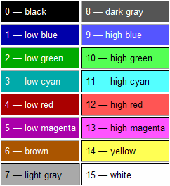
Those who have programmed or painted in DOS or Windows 3 / 98 before may remember these colors by heart, and this can speed op reading of the digits. For example, when you see this column pattern:
1 - white
1 - red
0 - green
1 - blue
You add up the colors mentally and see 'bright magenta' which you may immediately link to the number 13. (Or just use the classic way of adding 8+4+1 = 13)
The only extra thing you have to remember is that R+G+B is brighter than just White, which in itself is kinda logical if you think about it.
The LEDs are driven as a 5x4 bit matrix display (not Charlieplexing as the development board might suggest). Each second the display advances to the next time, eg. from 14:03:59 to 14:04:00. To prevent irritating flashes in the corner of your eye, the display gently fades from one time to the next using PWM with linear ramps.
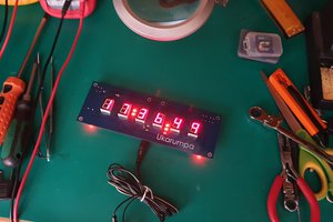
It keeps time by listening to the 50Hz frequency of the mains. It won't be able to keep time on battery without an additional RTC, and for 60Hz zones it needs some reprogramming. (Porbably just change 156 to 136 in the code, but don't blame me if there are other incompatibilities, like with the fading).


 Roni Bandini
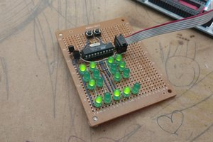
 Marius Taciuc
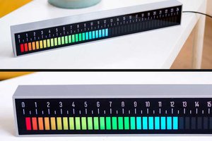
 Maakbaas
My understanding of Binary Coded Decimal is that 4 bits are used to represent the digits 0 to 9 and the codes that might otherwise represent the digits 10 to 15 are not used. It is inefficient but sometimes useful and I could certainly understand a clock using it but I don't think this clock does actually use BCD at all. BCD certainly doesn't typically involve a colour code.
What am I missing here?