Close
0%
0%

WDclock

Home made 7 segment clock housed in an external Western Digital hard drive enclosure

Similar projects worth following
Most consumer digital clocks have a chip in them capable of displaying 12 or 24 hour time, but most cheap out on the 4th digit, making it a "2 segment" display, as it can only display a "1" digit. I found this very annoying, as I prefer 24 hour time. The solution? Make my own fully featured clock, of course!

This all started when I tried hacking my cheapy Timex bed side clock to display 24 hour time. I looked up the datasheet for the clock chip inside and found it was capable of switching between both modes. I soldered up a switch, flipped it over to 24 mode, and tada! 24 hour mode! This worked great, until it came around to 8pm (20:00).
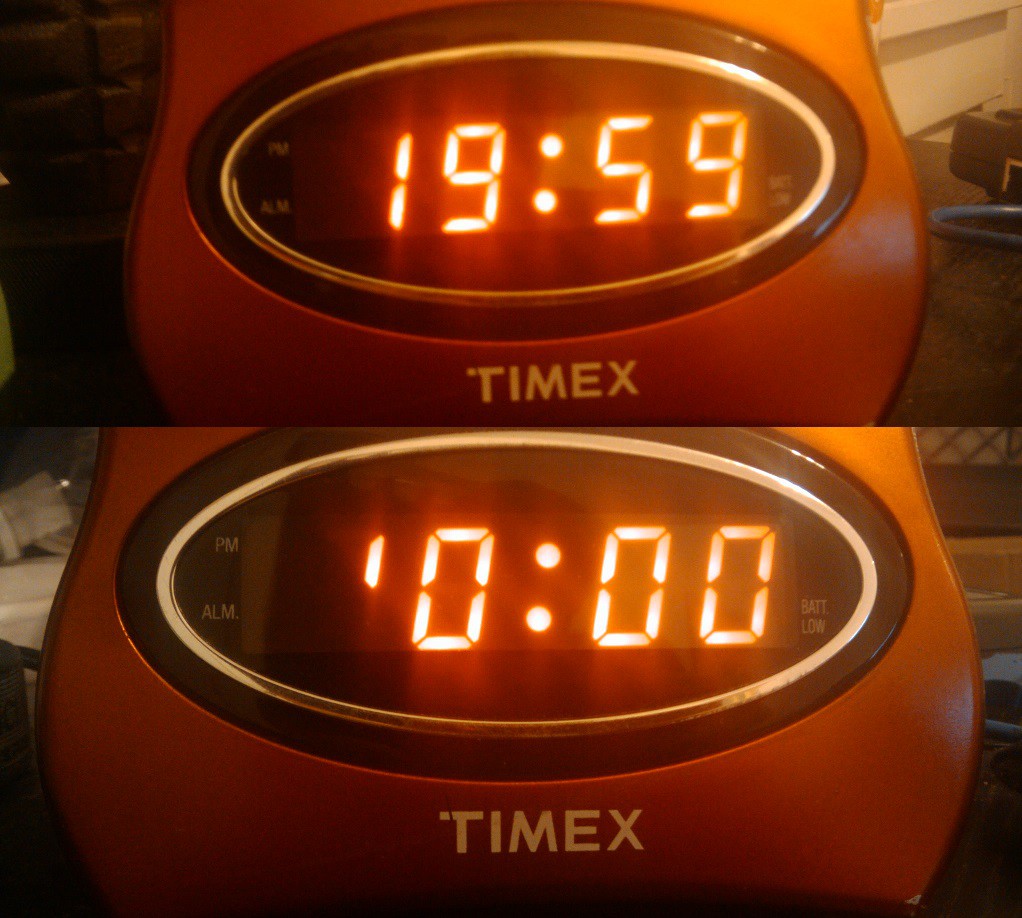
Some cost cutting engineer decided it would be a great idea to put a 7 segment in a clock which only had 2 usable segments! Seriously guys? I tore open several other cheap alarm clocks, and found this is aparently a common thing to do.

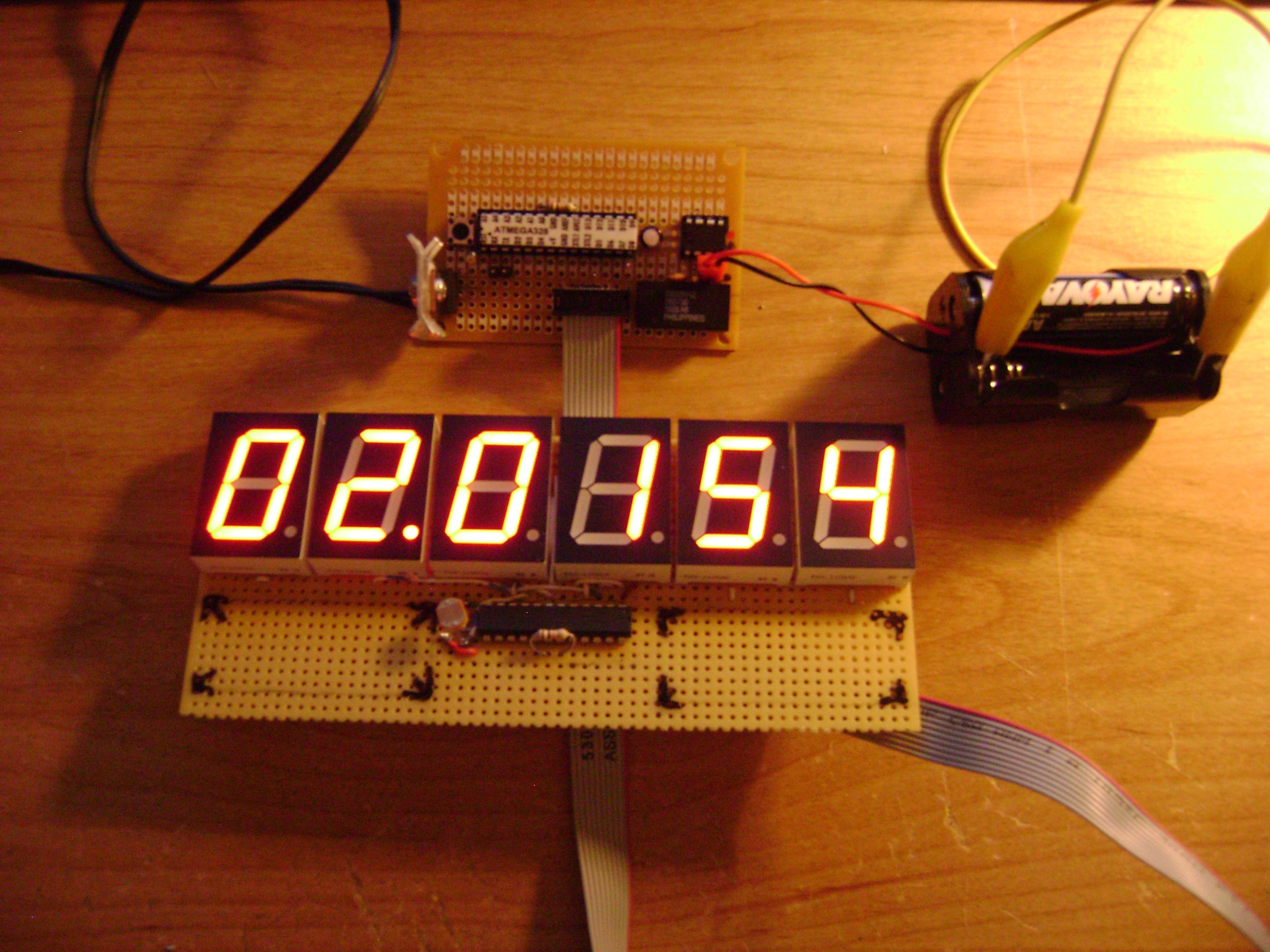
After a trip to my local American Science and Surplus, I had a pile of red 1.25" seven segment displays ready to wire up. After a prototype with an Arduino, I wired up 6 digits to a MAX7219, hand soldering jumpers between each digit. Note to self, next time use proto board with copper pads :P

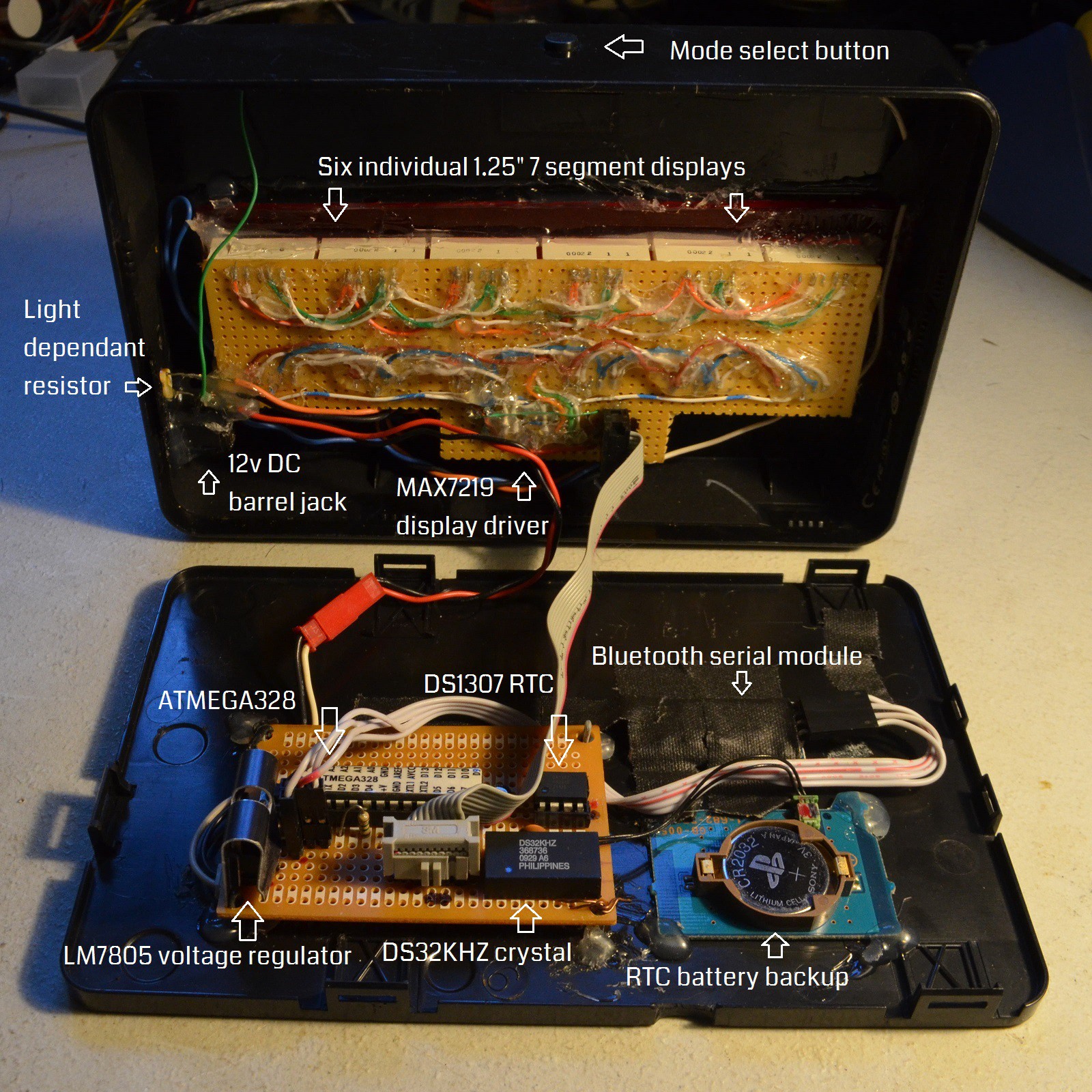
I soldered together a basic bread board version of an Arduino using an ATMEGA328. Add in a DS1307 real time clock, a DS32KHZ TCXO, a backup coin cell battery holder from a busted PlayStation 2, and a Light Dependant Resistor for dynamic dimming.
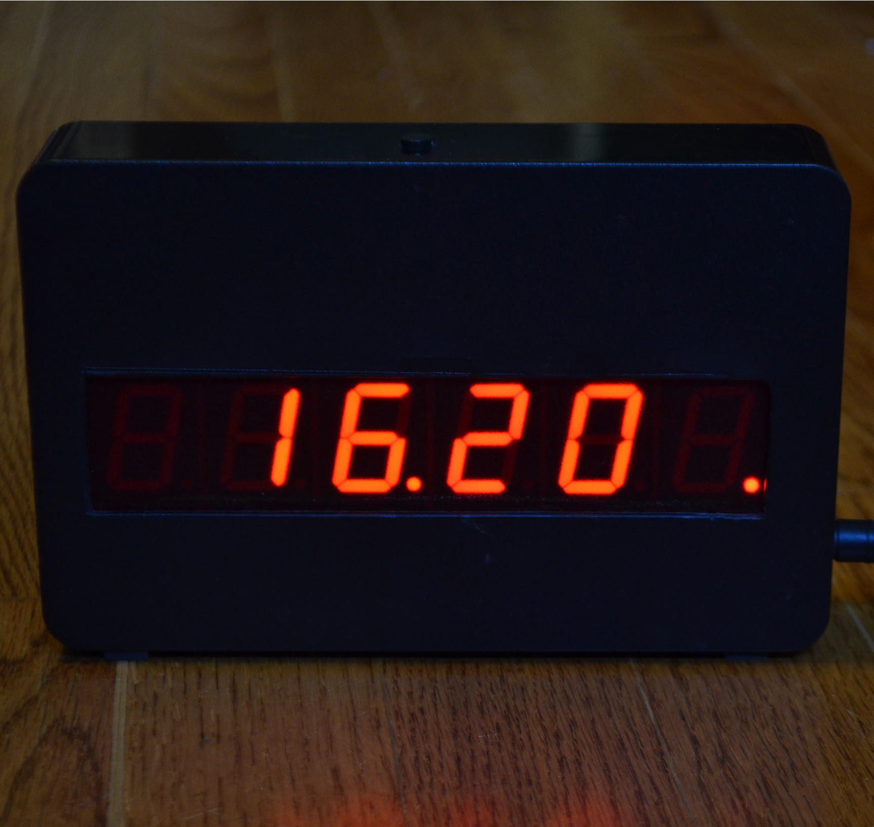
In its current state, the clock currently has 3 modes, switchable by the single tactile button on the top of the case. The first mode shows the current 24 hour time (hours and minutes only) with a blinking dot between the hours a minutes blinking on and off every second.

The second mode show the current date (day, month, year) with the dots between the day and month, and month and year alternating once per second.
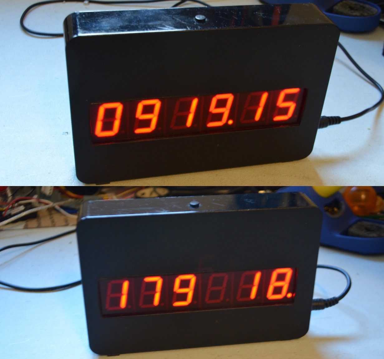
The third mode is count down clock to a user select-able date in the future (currently hard coded in the firmware). I have used this mode at the last few New Year's Eve parties I have attended/hosted, and its a big hit. When the countdown is greater than 24 hours, it displays remaining days and hours. Once below 24 hours, it counts down hours, minutes, and seconds. Once the event time has passed, it displays a message like "Happy 2015" or "Happy B-DAY".

The clock also contains a cheapy bluetooth to serial module, connected directly to the ATMEGA328's hardware serial pins. This allows me to run a script on my linux server which sends the current epoch time to the clock via bluetooth serial profile, which updates the onboard RTC. I had plans to send weather information via this bluetooth serial link as well, but have yet to implement it. The decimal point on the furthest right digit lights up for a few seconds after a successful update, as seen in a few of the above pictures.

The enclosure for the clock comes from a Western Digital external hard drive. This case is ideal because it snaps apart and back together very easily. The rectangular hole in the front was cut out with a laser cutter at my local hacker space.

I have toyed with a few additional modes, such as displaying the current 6 digit TOTP used to access my server, and adding temperature / humidity sensors.

Projects like this are never really done, but it is "complete enough" that it makes a fantastic bed side clock that does what I need it to do.

  • 1 × Atmega328P-PU Arduino compatible Microcontroller
  • 1 × DS1307+ DIP Real Time Clock
  • 1 × Tactile momentary button
  • 1 × DS32KHZ DIP TCXO 32.768kHz Crystal
  • 1 × MAX7219 Interface and IO ICs / Display Interface

View all 11 components

  • PCB design complete

    Gigawatts02/10/2020 at 20:51 0 comments

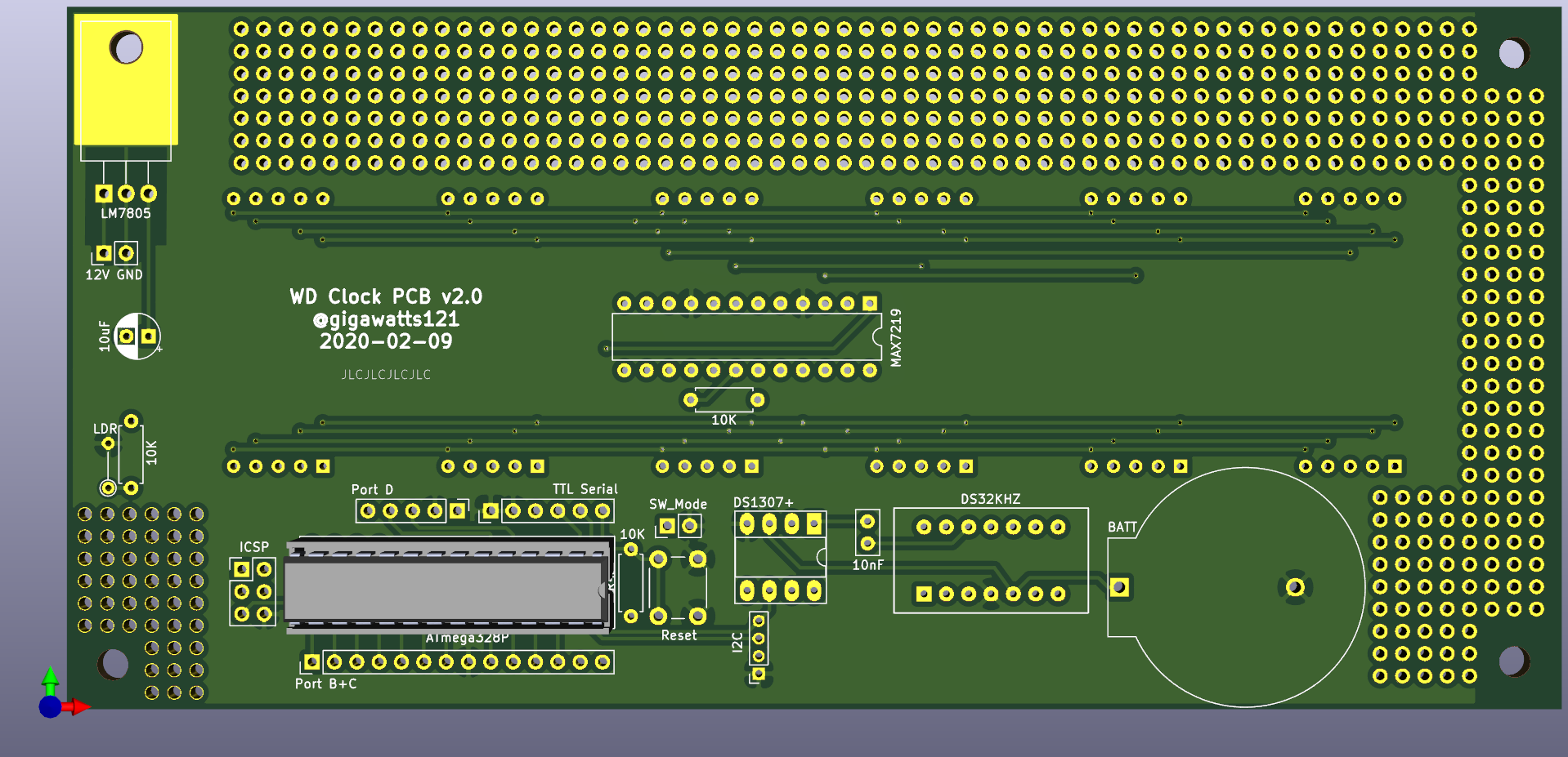
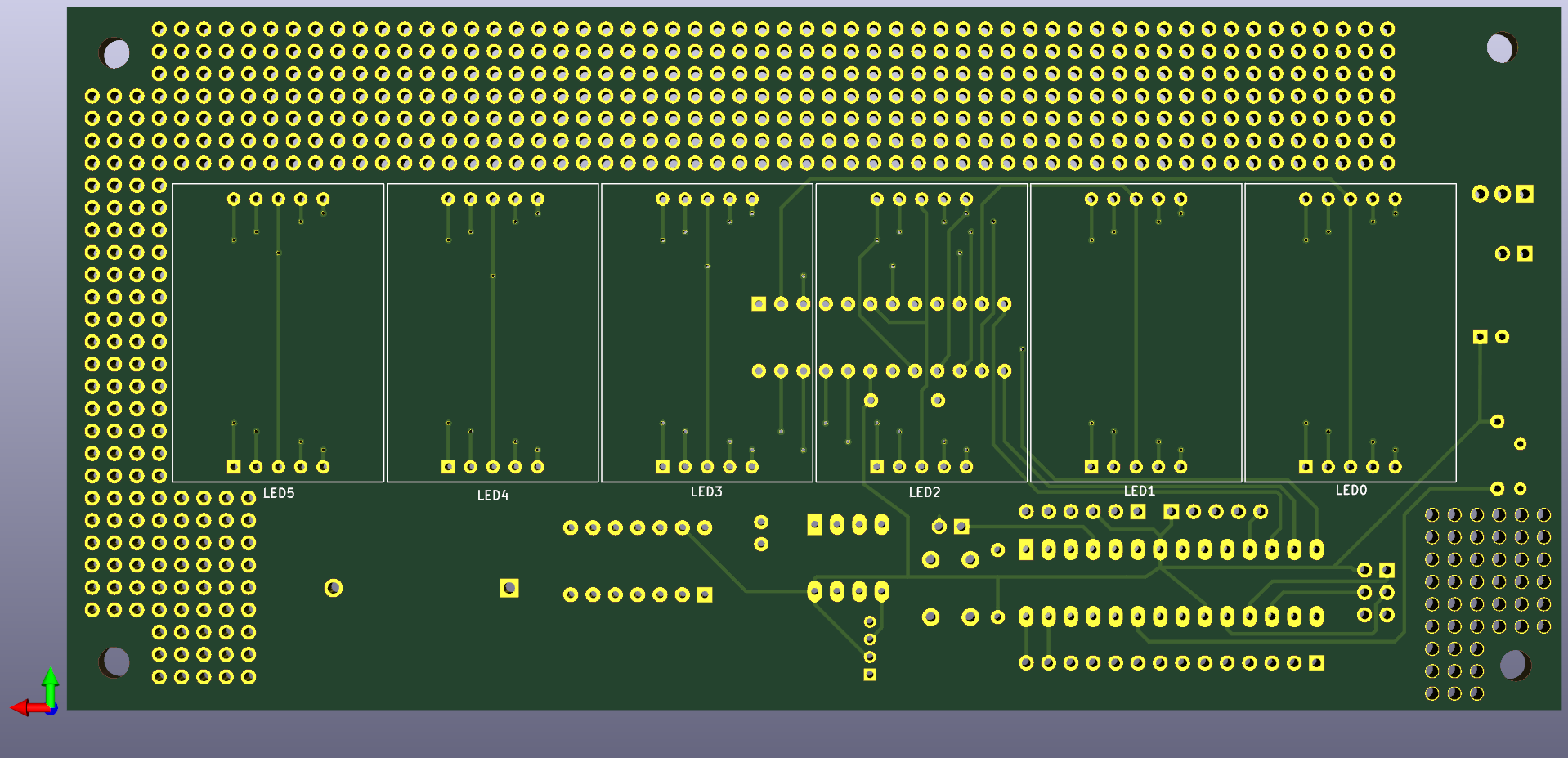
    Finished up the PCB design yesterday and sent it off to JLCPCB. I sure hope it works! I'll provide another update when I take delivery of the PCBs and transfer all the components over from the proto-board.

  • So I'm designing a PCB...

    Gigawatts01/21/2020 at 02:52 0 comments

    I still use this clock daily, though a few of the wires connecting all the segments together must be coming loose, as every so often a few segments will turn off. I can usually fix this by smacking or flexing the clock a bit, but this has become more frequent and more annoying.

    It's time for a real PCB!

    I have started re-designing this project in KiCad, but it is going slow, as I don't have much experience with PCB design software. I intended to have the PCB done before the due date for the Tell Time contest, but there is no way I'll be able to finish the design and have a PCB made in the next 4 days.

    Anyway, one real update I do have is some updated code. I finally (some time in the last year) added daylight savings time support to the clock, so it will automatically flip back and forth, even if the clock is "offline" (not receiving time updates via it's Bluetooth serial connection). Updated code can be found on github (https://github.com/gigawatts/WDclock).

View all 2 project logs

Enjoy this project?

Share

Discussions

meuviolino wrote 07/12/2019 at 22:14 point

Oh! Good to hear the news that you will redo the project with ESP8266 or ESP32; Maybe I'll wait. I have several of these displays, single and double;
Thanks for the answer.

  Are you sure? yes | no

meuviolino wrote 07/12/2019 at 01:04 point

Hi Ken, first of all, thank you for the shared project.
1) I did not understand how the 6 displays are connected; are they multiplexed? The schematic was confused for me.
2) Instead of the ATmega328, I would use an Arduino Nano, for example.
3) In place of DS1307, I would use a RTC Module DS1307 or DS3231.
Anyway, if you do not mind making a schematic (even simple), I thank you very much.

Daniel

  Are you sure? yes | no

Gigawatts wrote 07/12/2019 at 17:43 point

The LedControl library is written specifically to interface with the MAX7219 LED driver chip I used. It can drive up to 8 x 7 segment LED displays, or an 8 x 8 grid of LEDs. The MAX7219 chips can be daisy chained (they are addressable) to drive even more LEDs. The author of that library has a site ( https://www.pjrc.com/teensy/td_libs_LedControl.html ) which will provide you better details on how the chip can be wired up and used, with some great example code.


Substituting a different Arduino and/or RTC module should be a pretty simple change. I have considered redoing this project with an ESP8266 or ESP32 so that I can have the clock connect to WiFI and sync with NTP.

  Are you sure? yes | no

meuviolino wrote 06/17/2019 at 16:30 point

I did not find the Arduino sketch;

  Are you sure? yes | no

Gigawatts wrote 07/08/2019 at 20:37 point

I'lll work on cleaning up the source a bit and getting it posted this week.

  Are you sure? yes | no

Gigawatts wrote 07/11/2019 at 23:59 point

  Are you sure? yes | no

Similar Projects

Does this project spark your interest?

Become a member to follow this project and never miss any updates