Close
0%
0%

MSP430 Binary LED Clock

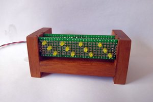
A Binary-Encoded Numerical LED clock, because those seem to be trendy these days.

Similar projects worth following

Welcome to my timepiece project using an MSP430G2553 chip.

This project, for now, will hold two core tenets.

  • Display local time via BCD in LED's.
  • Time is calculated and stored all on-chip, using timer peripheral interrupts.

I will be using the logs as a sort of tutorial on the thought process behind how the system works.

  • 1 × MSP430G2 Launchpad Microcontroller, this is the brains of the operation.
  • 3 × 74HC595 Shift Registers These are the drivers for the LED's.
  • 17 × LED's Choose any color you like.
  • 3 × Current Limiting Resistors for LED's (Roughly 220 Ohms) We're doing some multiplexing of lights. Only three lights are ever on at a given time, so we only need
  • 6 × Pullup/Pulldown Resistors (10k Ohms or higher) So that the shift registers work properly, we'll be pulling a few pins on the board high or low, and using resistors to do it.

View all 6 components

  • Code Log 1: MSP430 Real-Time Clock Setup

    W. Alex Best09/23/2015 at 17:51 0 comments

    So, these project logs on HaDIO are still kinda new to me, and since there's not a lot of "logging" to do since the project is largely done, I'll go over explaining the core components of the system inside.


    INITIAL SETUP

    First up, let's set up the base environment and initialize the internal timer so that we can actually keep track of time on the MSP430.

    #include <msp430.h>
    int main(void){
        //Disable Watchdog
        WDTCTL = WDTPW + WDTHOLD;
    
        // Set clock to 1 MHz
        BCSCTL1 = CALBC1_1MHZ;
        DCOCTL = CALDCO_1MHZ;
    }
    

    This is the base environment we'll be working with, and should be the base for most MSP430 projects.

    So far, we set the MSP430 to a rather slow 1 MHz, because we are using the internal clocks to keep track of time for our RTC (Real Time Clock). The slower the better, since then we can use smaller numbers for the passage of time.


    TIMER INITIALIZATION

    Now, let's write the initialization function for the timer peripheral.

    void timerInit(void){
        // Enable Timer Interrupts
        TACCTL0 = CCIE;
    
        // SMCLK, Count to CCR0 Value, Divide by 8
        TA0CTL = TASSEL_2 + MC_1 + ID_3;
    
        // 1,000,000 / 8 / 25 = 5000
        TACCR0 = 5000;
    }

    The first line enables the system to perform interrupt functions, which we will set up later.

    The second line sets up the way the timer will count:

    • TASSEL_2 defines that the timer clock will be based on SMCLK, sourced from the main clock, which we set to 1 MHz earlier.
    • MC_1 defines that the timer counter register will count up to the value stored in the TACCR0, then flag an interrupt, and reset to 0.
    • ID_3 defines that the timer counter will count up once for every eighth clock cycle of the SMCLK.

    This effectively means that the timer counter register will increment at 125 kHz.

    The last line defines the TACCR0 register as 5000. Meaning that the Timer Peripheral will call an interrupt at a frequency of (125 kHz / 5000) = 25 Hz.

    Finally, we just have to implement this function in our main function during initialization phase.

    int main(void){
        //Disable Watchdog
        WDTCTL = WDTPW + WDTHOLD;
    
        // Set clock to 1 MHz
        BCSCTL1 = CALBC1_1MHZ;
        DCOCTL = CALDCO_1MHZ;
    
        timerInit();


    TIMER INTERRUPT

    Let's move on to the actual contents of our timer interrupt.

    First, we're using global variables to store the clock data of our RTC. It's not the most elegant or safe solution, but hey, good enough for a quick weekend project!

    #include <msp430.h>
    
    #define RTC_STATE_SECONDS 0
    #define RTC_STATE_MINUTES 1
    #define RTC_STATE_HOURS 2
    
    volatile uint8_t timerCount = 0;
    volatile uint8_t rtcState[3] = {0, 0, 0};
    
    int main(void){
       /* ... */
    }
    The current state for the RTC is stored in an array of 8-bit values known as rtcState[].

    Now we define our actual interrupt function, get ready for a long one.

    // Timer Interrupt
    #pragma vector TIMER0_A0_VECTOR
    interrupt void Timer_A(void){
        timerCount++;
        if (timerCount >= 25){
            timerCount = 0;
            rtcState[RTC_STATE_SECONDS]++; 
            if (rtcState[RTC_STATE_SECONDS] >= 60){
                rtcState[RTC_STATE_SECONDS] = 0;
                rtcState[RTC_STATE_MINUTES]++;
                if (rtcState[RTC_STATE_MINUTES] >= 60){
                    rtcState[RTC_STATE_MINUTES] = 0;
                    rtcState[RTC_STATE_HOURS]++;
                    if (rtcState[RTC_STATE_HOURS] >= 24) {
                        rtcState[RTC_STATE_HOURS] = 0;
                    }
                }  
            }
        }
    }
    Since the timer is flagging an interrupt at 25 Hz, first we increment the timerCount variable. When it reaches 25, we reset it to 0, and increment the rtcState variable denoting the seconds. From there we do the typical cascading check to see if we increment the minutes count, or hours count. Note our use of 24-Hour time keeping, rather than having a seperate variable for AM/PM checking. We can use this as we please later.

    I believe that covers most of the functionality for actually having an RTC internal to the MSP430G2553 chip, without relying on any external peripherals.

    It's worth noting that the accuracy of the RTC is not very high, and the clock is likely to drift and be inaccurate. In order to improve accuracy, we can include external hardware, such as a dedicated hardware RTC, like the DS1307, which I may actually...

    Read more »

View project log

Enjoy this project?

Share

Discussions

Similar Projects

Does this project spark your interest?

Become a member to follow this project and never miss any updates