Close
0%
0%

SPI Flasher

Got a Raspberry Pi ? A few more bucks turn it into a networked SPI Flash chip reader/writer

Similar projects worth following
A small PCB (extension bus to DIP-8 adapter) and a well configured SD card are all you need to turn your RPi into a SPI Flash programmer/dumper that you can use from the command line or your browser!

Written originally for WizYAsep http://wizyasep.com in C for Linux, only the low-level routines (GPIO and SPI) are specific to the Raspberry Pi. A smart programming algorithm has been developed to reduce wear.
This system was integrated in the YGWM framework and uses the HYX file format.

It is currently limited to 3.3V chips with 24-bits addresses (128KB to 16MB capacity). I have validated 25LC1024, M25P40, A25L40P, AT26DF321, W25Q32BV, W25Q64, W25Q128F. Please contribute your own chips :-)

Raspberry Pi 2/3 compatibility is coming.

The purpose of this project is to support the #YASEP and other Free Hardware Designs with the help of a device that is :

  • Cheap: no significant investment so even beginners can do it
  • Compact and autonomous : can operate with a battery pack for easy handling on site (yes I have used mine outdoors in winter with no access to mains...)
  • Easy to make yourself : simple, easy to find components, no hard-to-solder parts...
  • Based only on Free Software (Affero GPLv3+ is chosen for everything)
  • Exempt of any proprietary technologies (directly or indirectly), such as USB: no driver or configuration to do for the user (you can use any OS or browser)
  • Plug&Play : connect it to your computer or the local hub, point your browser to the IP and start playing.
  • Perennial : store it for years on a shelf without fear of obsolescence.
  • Powerful through integration with other modules from the YASEP framework

A Flash SPI programmer is an essential engineering tool that has been done over and over. I built my first LPT-based SPI programming dongle around 2004, using instructions found on the Web. It was cheap and smart, stealing the power supply off the pull-up resistors, but you know what happened to the parallel printer port... Do you even have one left somewhere ?

Today most interfacing duties are performed over USB but this creates a whole lot of problems that will make me digress and rant.

Fortunately Ethernet is one of the last communication ports that still remains in today's cost-conscious consumer (autistic) "PC"s. It requires no driver or explicit configuration (nowadays DHCP is the norm) and TCP/IP is a venerable, well understood protocol that reaches wayyyy beyond the boundaries of your desk. You can use the programer on a desk across the room, in another room, in another building or...

The Raspberry Pi also bridges the gap between sophisticated OS and IO bitbang, along with affordability and availability. Its success strengthens the world of the Linux nanoPCs, where the competition benefits everybody and reintroduces directly-accessible IO pins !

Deciding to host the YGWM framework on a Pi was a natural choice, despite Pi's shortcomings (let the competition do its work :-D). For a Free Hardware Design project to succeed, it is essential that the entry barrier remains as low as possible and now most hackers have a nanoPC or two to tinker with. Turning a Pi into a SPI master interface requires little additional hardware so the differentiation comes from the software and its integration.

The OS is derived from Raspbian, my version is #Raspbian Squeezed that can work without monitor and can be abruptly powered off without any risk.

The flashing program tries to do one thing and do it well. It is a single C program working as a CGI with the standard Apache HTTP server. It handles a custom file format called .HYX that is easy to understand, parse or generate. The trick is that it can support other file formats through the use of filters, like oldfashioned UNIX programs. UNIX filters are already provided to export/import in JSON and raw binary formats. Better yet: through its integration with the #YGWM tools, you can import data from other sources and create your own filters in JavaScript, which keeps the C file short and clean.


Logs:
1. Adding a new part: the Winbond 25Q32
2. Software updates
3. A little speed comparison
4. Todo...
5. Updates


20170501:

The rebuilding work has started, with the now working #C GPIO library for Raspberry Pi a (which now supports Pi2 and Pi3) #C SPI library for Raspberry Pi. It will take a while to get the whole stack working nicely again but this is on my roadmap...

W25Q128F.pdf

octetstream - 1.30 MB - 11/06/2016 at 13:53

Preview

Winbond_25Q64BV.pdf

octetstream - 1.69 MB - 11/06/2016 at 13:53

Preview

w25q32bv_revi_100413.pdf

octetstream - 1.07 MB - 11/06/2016 at 13:53

Preview

M25P40.pdf

octetstream - 1.13 MB - 11/06/2016 at 13:52

Preview

AT26DF321.pdf

octetstream - 653.38 kB - 11/06/2016 at 13:52

Preview

View all 11 files

  • 1 × Raspberry Pi B or B+ Type 2 not yet supported but planned
  • 1 × pre-drilled prototyping board
  • 1 × DIP8 socket or ZIF or SOIC8 if you need
  • 1 × obligatory 100nF ceramic capacitor
  • 1 × Software "it works for me" but needs to be repackaged

  • Updates

    Yann Guidon / YGDES04/15/2016 at 17:24 0 comments

    I submitted this project to the Hackaday Prize 2016 because I welcome incentives to turn it into a full spin-off of the #YASEP Yet Another Small Embedded Processor project. Now I see it is tangled in a web of co-dependencies with other subprojects and co-projects such as #Raspbian Squeezed.

    What works ?

    At home, it works great on a Raspberry Pi model B, using an obsolete version of the YASEP web interface, based on the the old #YGWM Whygee's JavaScript Window Manager system. The flashing algorithm is great (better than my commercial chinese flasher) and the source code is available from the main yasep.org project base (see links on the project page)

    What is missing ?

    You know the saying, if it ain't broken, don't fix it ? Well it works for me so why work further ?

    The problems however are piling up and might break the whole thing one day or another.

    • The Raspberry Pi hardware is not the stable, trusted platform it seemed to be. New PCB versions and new CPUs have been introduced at (relatively) breakneck speed and I assume it will continue (until the Pi foundation throws the towel).
      I have not yet updated my custom SPI routines to adjust the IO address of the SPI hardware. Why did they change it in the PI2 ?
      Anyway, it's one of the first things to do, but it requires non-insignificant attention and testing. I have already too many projects and I ain't even working on the side or being paid so...
      UPDATE20161106: I'm adding new sub-projects #C GPIO library for Raspberry Pi, #HYX file format and soon the SPI library.
    • The OS is not stable either. Raspbian has evolved a lot and even changed face. It has bloated and this has raised many concerns, not just from me. A reliable, small-footprint Linux is needed and maintaining the #SPI Flasher involves restarting a full system install every 6 months or so, which takes a day or three to get right. Scripting does not help when the OS modifies this and that in my back :-(
      Without this, the only way to run a SPI flasher is to install a vanilla image, log in with SSH and run the commands on the command line. Which is slower than the intended method through the web browser. Oh wait, that's another story.
    • The #YGWM Whygee's JavaScript Window Manager must be rewritten from scratch. That's a few months of work, that I don't have :-(

    So for a winning entry in the HaD contest, I can't submit the project as it was intended, I must reduce the ambitions. But I've already gone pretty far since the beginning of this project :-)

    Hopefully, one day, I'll be able to provide a pre-configured image to flash on your SD card with instant boot to the desired functionality. But this looks more and more like shooting many moving targets at the same time. I can adapt things here and there, YGWM is a project that I fully control and will develop, but I am growing tired of having to play catch with the Pi Foundation's whims.

    Of course the solution would be to have a working #YASEP Yet Another Small Embedded Processor but I must bootstrap the whole platform somehow, somewhere.

  • Todo...

    Yann Guidon / YGDES01/19/2016 at 13:30 0 comments

    The .hyx files can get large. Pretty large. A 16MB flash chip requires 32 or 48MB of storage. I should add support for Zlib, which provides transparent support of gzip-compressed data...

    Until I do it, thanks to posixity, it's possible to write this, when the original file is compressed :

    gunzip file.bin.gz
    bin2hyx file.bin | update_SPI_flash -

  • A little speed comparison

    Yann Guidon / YGDES12/03/2015 at 02:32 0 comments

    Sorry for the lack of updates, I'm pretty busy everywhere but I don't forget this project ! Thank you everybody for (still) following it :-) Your interest motivates me !

    For another application, I just got a TL866 USB universal programmer and it's working rather well. Most of the time. I'm testing some W25Q128 chips I just bought for a project and several would fail when writing the chip with all 0s. Repeatedly on the same chips, but not others of the same lot. Weird. Is this batch of chip mixed with bad apples ?

    Fortunately I have the Pi SPI Flasher and I found that the chips have been properly written. So what happened ? It might be the TL866 as well because my algorithm finds no error. Maybe the TL866 tries to be too agressive ? Why are there reading errors on some chips and not others ?

    I've also run another simple test:

    $ time ./update_SPI_Flash zero16M.hyx verbose DIV 24
    ...
    Writing 256 bytes to address FFFD00
    Writing 256 bytes to address FFFE00
    Writing 256 bytes to address FFFF00
    * Pass 2
     Checking the sector
     Checking for page to write...
      Sector : OK with 2 passes.
    
    16777216 bytes written.
    
    fermeture SPI
    Setting pins 8 9 10 11 22 as input
    Flash programming OK
    real    2m41.221s
    user    1m49.320s
    sys     0m16.060s
    

    (note: it was run over ssh which uses some CPU...)

    Whereas the TL866 took 7 minutes 23 seconds to do the same task.

    I guess I will not use the USB programmer for this kind of SPI chips (particularly when I have tens of chips to test). I also see that my programming algorithm is better/smarter than the TL's :-) It's both faster and more accurate.

    More reasons to continue this project ;-)

  • Software updates

    Yann Guidon / YGDES09/25/2015 at 20:11 0 comments

    This SPI flasher is part of a much larger project. As the whole system grows, so does each part and a spin-off becomes necessary for reliability and stability.

    I want to make a high quality system with a great tutorial that most DIYers can follow. All help and feedback is welcome ! Who would like to test the tutorial ? Who wants to add parts to the list of supported chips ? What other features are needed ?

    The documentation has grown fast so far but it's going to stall for a very common reason: it will deal now with software. Software development is slow. Hardware design is comparatively simple, easy and fast. Software is the quicksand of computing. Please excuse me for the delays ;-)

    I have developed quite a bit of software and I have a working and cool Flashing system at home but the spin-off requires a complete review of all the code, a deep rafactoring to make it totally stand-alone and suitable for your use. Your help is again more than welcome. My plan includes a total rewrite from the ground up:

    • get a Pi2 board (I'm using B and B+ now but many use the newest shinier ones) but I'm so broke right now... => done thanks @bsteph27 !
    • create a suitable Raspbian derivative => ongoing as #Raspbian Squeezed (please be patient)
    • Modify the GPIO and SPI code to support BCM2836 (not hard)
    • Write a CPU-agnostic SPI version with bit-banging (for other platforms, even a PC-LPT one ?)
    • Include support for #DIPSY (easy)
    • Make the source code easy to download, compile and use...
    • I can host small packages but how to distribute a large Pi OS image without breaking my server ? ==> see #Raspbian Squeezed and its scripts

    As you see, writing this page is only a tiny part of all the required development. How could you help me ?

  • Adding a new part: the Winbond 25Q32

    Yann Guidon / YGDES09/22/2015 at 23:04 0 comments

    The Winbond 25Q128 is a really cool part : high capacity (16 MBytes), very fast, good support for many standard instructions, supports wide bus modes... But it can be expensive depending on the application.

    I found the little sister 25Q32 : I use 6 of them on each board of a project. I expect it to be almost exactly the same as the 25Q128 but with only 4MBytes (so the board has 24MB, still nice). I got them off eBay and received them. Now comes the time to try them !

    As I am writing a detailed tutorial, I want to use this project log to show how to add a part to the SPI flasher so others can add their own (and as much as possible provide feedback so I can make this system better, for me and everybody else).

    First, let's get the datasheet !

    Google gives the right PDF on the first result when I type "datasheet 25q32bvsig". The file is on the Winbond website and I miror it on my own site http://ygdes.com/pdf/Flash/, for archival and easy retrieval.

    Let's analyse the data :

    • The device operates on a single 2.7V to 3.6V power supply : 3.3V compatible voltage : check
    • Standard pinout : check
    • 256-byte per programmable page : Page Program instruction (02h) accepts up to 256 bytes : check
    • Clock frequency for Read Data instruction (03h) 50 MHz max : check
    • Uniform Sector/Block Erase (4/32/64K-bytes) : Page Erase instruction SE (0xD8) erases one 64KB block : check
    • nothing sounds unusual...

    More analysis is necessary to complete the description and table in SPI_Flash_chips.h but it seems to follow the 25Q128's definitions so this is just a matter of checking that every instruction matches.

    The 25Q32 follows all the conventions so it's safe and easy to use with the flasher. I can update SPI_Flash_chips.h :-)

    Let's now solder !

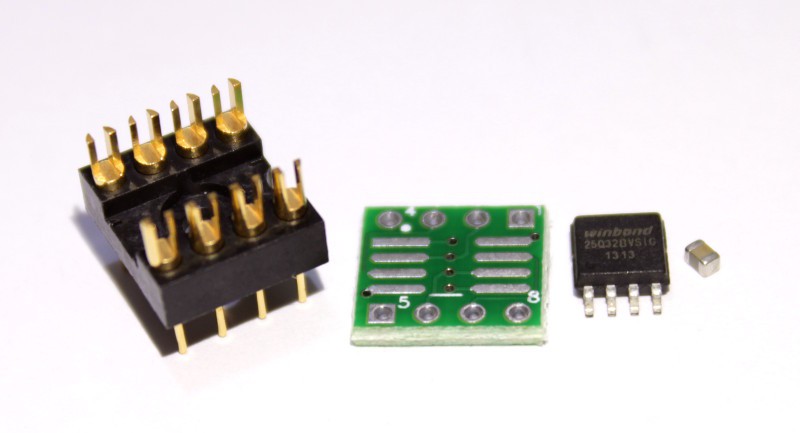
    I also bought some tiny DIP8-SOIC8 adapter boards on eBay so I can test them in the common DIP8 socket. I have a SOIC ZIF somewhere but it's not very practical. The PCBs need pins too: these come from special DIP8 sockets that I hacked a bit and provides a sturdy base, but you'll use your own parts.

    This time I put the capacitor directly close to the chip's power supply pins.

    Now I can test it !

    I power the Raspberry Pi on, looking at the HDMI screen that displays the boot logs.

    My IP address is 192.168.41.100
    
    pi login: _
    I see that Apache is working when I browse to http://192.168.41.100/ and I access the YGWM interface. I can now login through ssh:
    [yg@localhost ~]$ ssh pi@192.168.41.100
    pi@192.168.41.100's password: pi
    Linux pi 3.12.28+ #709 PREEMPT Mon Sep 8 15:28:00 BST 2014 armv6l
    /dev/root on / type ext4 (ro,noatime,errors=remount-ro,data=ordered)
    remount RW
    pi@pi ~ $ _
    
    This Pi boots in "read only mode" so you can turn it on and off without concern of filesystem corruption.

    The software tools are installed in the Apache data directory. I go there to execute one of the test programs:

    pi@pi /var/www/C $ sudo ./test_SPI_Flash 
    
    SPI Flash Signature :
     EF 40 16 00 00 00 00 00
     15 15 15 15 15 15 15 15
    Status Register = 00
     * Ready
     * Write disabled
     * Array is unprotected
    {
      start=0,
      data=[
    83,0,41,29,133,3,64,18,0,12,127,0,125,0,123,128,
    18,0,8,126,0,127,4,125,255,18,0,10,144,255,0,224,
    ...
    1,184,0,0,0,0,0,2,1,191,67,111,112,121,114,105,
    103,104,116,32,49,57,57,57,45,50,48,49,48,44,32,97 ]
    }
    
    Setting pins 8 9 10 11 22 as input
    
    It dumps the 256 first bytes of the Flash array into a JSON string and it is surprisingly not empty.

    I can now copy the extracted signature (very similar to the 25Q128) and paste into the chips library :

    pi@pi /var/www/C/src $ nano SPI_Flash_chips.h
    
                          0xD8   0x03            Bulk
                         Sector   Page  Freq     Erase    Test            Signature
                   Mbits  Erase  write  (MHz) (s)  (DS)   R/W     RDID            RES
    25LC1024        1     32KB    256     10   0?  (2-4)   OK    (0)+            (29)+
    M25P40          4     64KB    256     75   5 (4.5-10)  OK   20 20 13 (00)+   (12h)+
    A25L40P         4     64KB+   256     85   2  (6,12)   OK   (7F 37 20 13)+   (12h)+
    SST25VF016B    16     64KB      x     50               KO   (BF 25 41)+      (BF 41)+
    SST25VF032B    32     64KB      1     80               1o   (BF 25 4A)+      (BF 4A)+
    AT26DF321      32     64KB    256     66  39           OK   1F 47 (00)+      (00)+  (sold protected)
    W25Q32B        32     64KB    256    104   5 (7-15)    OK   EF 40 16 (00)+...
    Read more »

View all 5 project logs

  • 1
    Step 1

    First, build the DIP8 adapter.

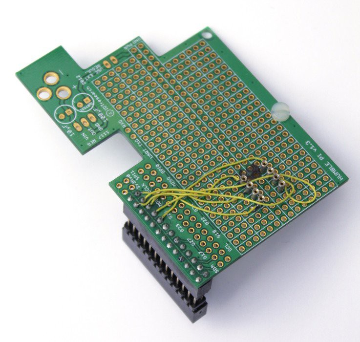
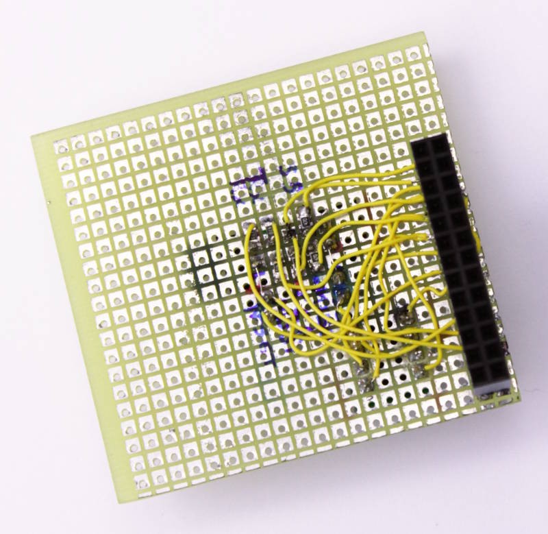
    This is not a complex circuit, here is one I made for the Pi:

    Required parts :

    1. PCB (a simple prototyping board is enough)
    2. some thin wire
    3. a female connector to plug on the Pi's extension bus (2×13 or 2×20 pins)
    4. a DIP-8 socket. Or a suitable ZIF socket.
    5. Not show above : the obligatory 100nF capacitor between GND and 3.3V supply close to the socket.

    That's a few €/$ at most.

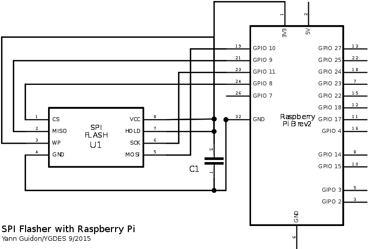
    The soldering part is not hard : GND, 3.3V and 4 data signals:

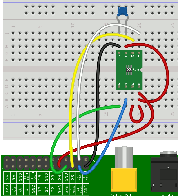
    For the breadboard fans, here is the wiring:

  • 2
    Step 2

    The console.

    OK I admit, I lied. This is not a SPI Flasher but a cog in a larger development environment. I designed this system to access the #WizYasep's "console port" so you can skip this part if you're not interested in cheap FPGA hacking (or the WizYasep).


    My "production" flashing board has a HE10 header to help develop and debug configurable logic. I developped the following interface because existing JTAG debugging systems are proprietary, often expensive and not portable across vendors (my system works whether you're A, L, M or X).

    This "console" port provides a slave SPI interface, a full-duplex asynchronous serial interface and an external RESET input (very handy). Another signal controls the function of the FPGA's pins : either user/design function (GPIO mode?) or "console" function (with SPI and serial data available, plus external control of /RESET). Of course, be careful to design a circuit that can still work when its GPIOs are not connected to the outside world ;-)

    The SPI signals are further multiplexed inside the FPGA and the debugged design can also work as a SPI slave. The external RESET signal selects who gets the data: FPGA slave when high (normal operation, where the FPGA can also access the Flash to fetch data), or external SPI chip when low (bypass mode, signals are routed from a pin to another). This is "transparent" and irrelevant when there is no FPGA (directly connected to the SPI chip) or if the FPGA contains an empty design.

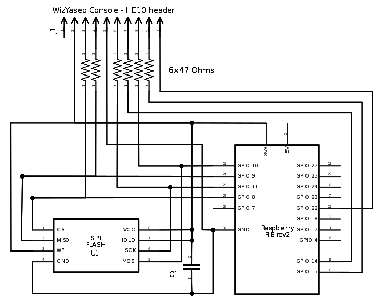
    Here is the HE10 pinout :

    1. unused (yet)
    2. IO mode (0V=GPIO, 3.3V: console) (FPGA pulldown)
    3. RPi SPI Slave Select (0V: bypass to Flash, 3.3V: internal slave) (FPGA pulldown)
    4. RPi SPI MISO
    5. GND
    6. RPi SPI CLK (FPGA pulldown)
    7. RPi serial TxD (FPGA pulldown)
    8. RPi SPI MOSI (FPGA pulldown)
    9. RPi serial RxD
    10. RESET input (0V: normal FPGA operation, 3.3V: freeze the FPGA and SPI bypass) (FPGA pulldown) (yep this is inverted from the usual designs but for a good reason)

    (note: all signals must be compatible with 3.3V CMOS ! They are also protected with a 47 Ohms resistor on the RPi side, in case the FPGA is in GPIO mode by accident)

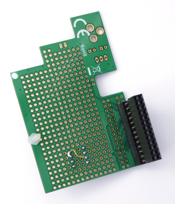
    The RPi is connected to the HE10 header with the 4 SPI signals, the 2 serial signals and another GPIO (n°22) is required to toggle the RESET signal and enter into SPI bypass mode (RESET is set to 1 during programming, the FPGA design restarts immediately when it's done). The "IO Mode" signal is tied to 3.3V and fixed to console mode (unless you want to play with it). The other side of my everyday board looks like this :

    There, you see, adding serial signals and a RESET output does not make a significant difference between the vanilla SPI Flash programmer and the more advanced FPGA debugger system... I keep the DIP8 socket on the board in case I need to test new parts or to check the RPi side is working correctly (in case of heisenbug).

  • 3
    Step 3

    Test the signals on the socket, to validate the wiring.

    You wouldn't want the magic smoke to escape and render your circuit(s) useless! A short circuit or a mistake is so easy and devastating... Use a white LED tied to GND and to the desired signal (white LEDs easily stand 3.3V without a series resistor), or a multimeter, to check that all the pins are correctly connected.

    First, check the signals as output. With a Python or bash script, make the following GPIO blink :

    • GPIO8 should blink the SS signal (pin 1 of DIP8 and pin 3 of console)
    • GPIO9 should blink the MISO signal (#2 of DIP8 and #4 of console)
    • GPIO10 : MOSI signal (#5 of DIP8 and #8 of console)
    • GPIO11 : SCK (#6 of DIP8 and console)
    • GPIO14 : TxD (#7 of console)
    • GPIO15 : RxD (#9 of console)
    • GPIO22 : RESET (#10 of console)

    Make sure to return each pin to "input" function after it is tested!

    Bash scripts are provided there https://hackaday.io/project/17066-c-gpio-library-for-raspberry-pi/files or http://ygdes.com/sources/Pi/

    Then connect a wire from the SCK pin (#6) of DIP8, to MOSI (#5 of DIP8). Turn SCK on and off and read the state of MOSI:

    GPIO_on.sh 11
    GPIO_in.sh 10
    # --> "GPIO10 =1"
    GPIO_off.sh 11
    GPIO_in.sh 10
    # --> "GPIO10 =0"
    # return to input mode :
    GPIO_in.sh 11
    You can also tie RxD to TxD (loopback between GPIO14 and GPIO15) and send data to check that the HE10 connector is correctly wired.

View all 8 instructions

Enjoy this project?

Share

Discussions

Yann Guidon / YGDES wrote 10/22/2015 at 20:02 point

Just to let you know : I am amazed by the interest this project generates :-)

Thanks everybody for the "follows", I'm doing a lot of other things but I'm still working on this particular project. Right now I have to solve OS image issues.

And your feedback is always welcome !

  Are you sure? yes | no

Antti Lukats wrote 09/20/2015 at 16:56 point

DIA?

  Are you sure? yes | no

Yann Guidon / YGDES wrote 09/20/2015 at 16:59 point

  Are you sure? yes | no

Yann Guidon / YGDES wrote 09/22/2015 at 03:39 point

There, I've done it and added a Fritzing sceenshot. Are you happy now ? ;-)

  Are you sure? yes | no

Antti Lukats wrote 09/20/2015 at 16:43 point

would be nice to add Fritzing sketch that shows the connections? it can be done in like 5 mins :)

  Are you sure? yes | no

Yann Guidon / YGDES wrote 09/20/2015 at 16:50 point

Hey I only started the project and have several others brewing at the same time ;-)

I have DIA already running but I'm multitasking ;-)

  Are you sure? yes | no

Similar Projects

Does this project spark your interest?

Become a member to follow this project and never miss any updates