Close
0%
0%

Bike Powermeter

A 2-part bicycle powermeter. Swap between bikes without tools in 5 seconds.

Similar projects worth following
I have too many bikes at home. A road bike for racing, one for training, one for winter, a cyclocross bike and a MTB. Training with a powermeter is really cool, but buying powermeters for all my bikes is far beyond my budget. Of course there are powermeters which can be switched between bikes in several minutes, but e.g. pedal based systems for road bikes are not a good idea on a MTB.
Thus, I designed my own 2-part crank-based powermeter. The idea is to put parts on the crank arm which need to stick to the crank arm only. All other electronics are detachable and can be swiched between bikes in a few seconds. Really easy and fast.
The parts which are glued to the crank permanently are very cheap. Thus, fitting the measuring unit to all your bikes is also cheap. Only one single powermeter unit which is more expensive and carries all the electronics for analysing data and sending it via ANT+ to your bike computer is needed.

The pictures show the powermeter unit (powermeter as well as measuring unit permanently glued to crank). The measuring unit in the pictures is fixed with a rubber band, this will be omitted in future designs. The pictures also show the charging unit, a debug unit which can be attached between measuring unit and powermeter unit (for firmware updates and sniffing data) as well as a tool for calibrating the measuring unit with known weights.

Currently, calibration and comparison with my Elite Kura smart trainer as well as Garmin Vector 2s is ongoing. Comparison charts and further details coming soon. 

  • 1 × Atmega 328p CPU
  • 1 × MPU6050 Gyroscope for cadence. Using DMP currently which consumes a lot of power.
  • 1 × nRF24AP2 ANT+ communication
  • 1 × M24C64 EEPROM for storing e.g. calibration data in crank-part of power meter.
  • 1 × HX711 ADC for strain gages. This one is really low-cost. We will see how it does its job when e.g. temperature changes.

  • In-saddle versus out-of-saddle

    rock-o-mat03/27/2018 at 01:03 0 comments

    I am still testing against my Elite Kura and Garmin Vector 2s. I calibrated the scale with only one known weight and assumed a linear relationship between torque and weight. It is close, but not close enough. There is a significant deviation between riding standing or sitting at the same power. 

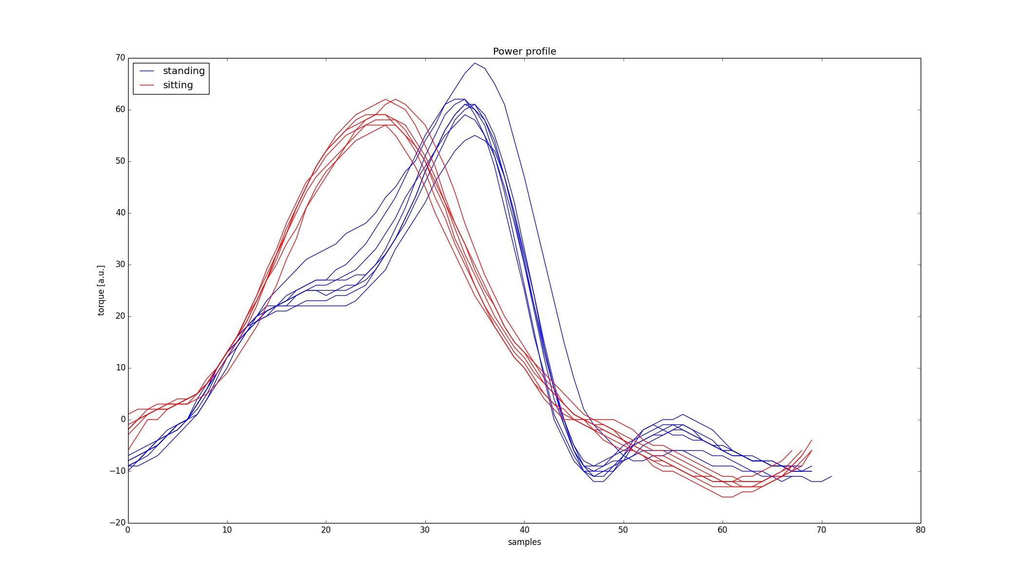
    The plot below shows the torque profile for one crank revolution. Standing and sitting cadence and power output was identical (as measured with Elite Kura and Garmin Vector 2s). However, my power meter measured 230W for sitting and only 220W when standing. 

    The integrals for red and blue curves should have been equal, but they are not. The in saddle position gives a more smooth torque profile with a peak around sample 25. The out of saddle position peaks at sample 35 and differs in shape. The blue curves are only slightly higher than the red ones, in order to give the same power reading they should have been giving higher amplitudes at the peak. I assume that for higher torques the crank bends less and less. 

    So, we have some nonlinearity here. I already included a second order term in my torque calculation which takes care of this. 

  • First test ride (indoor)

    rock-o-mat03/21/2018 at 09:14 0 comments

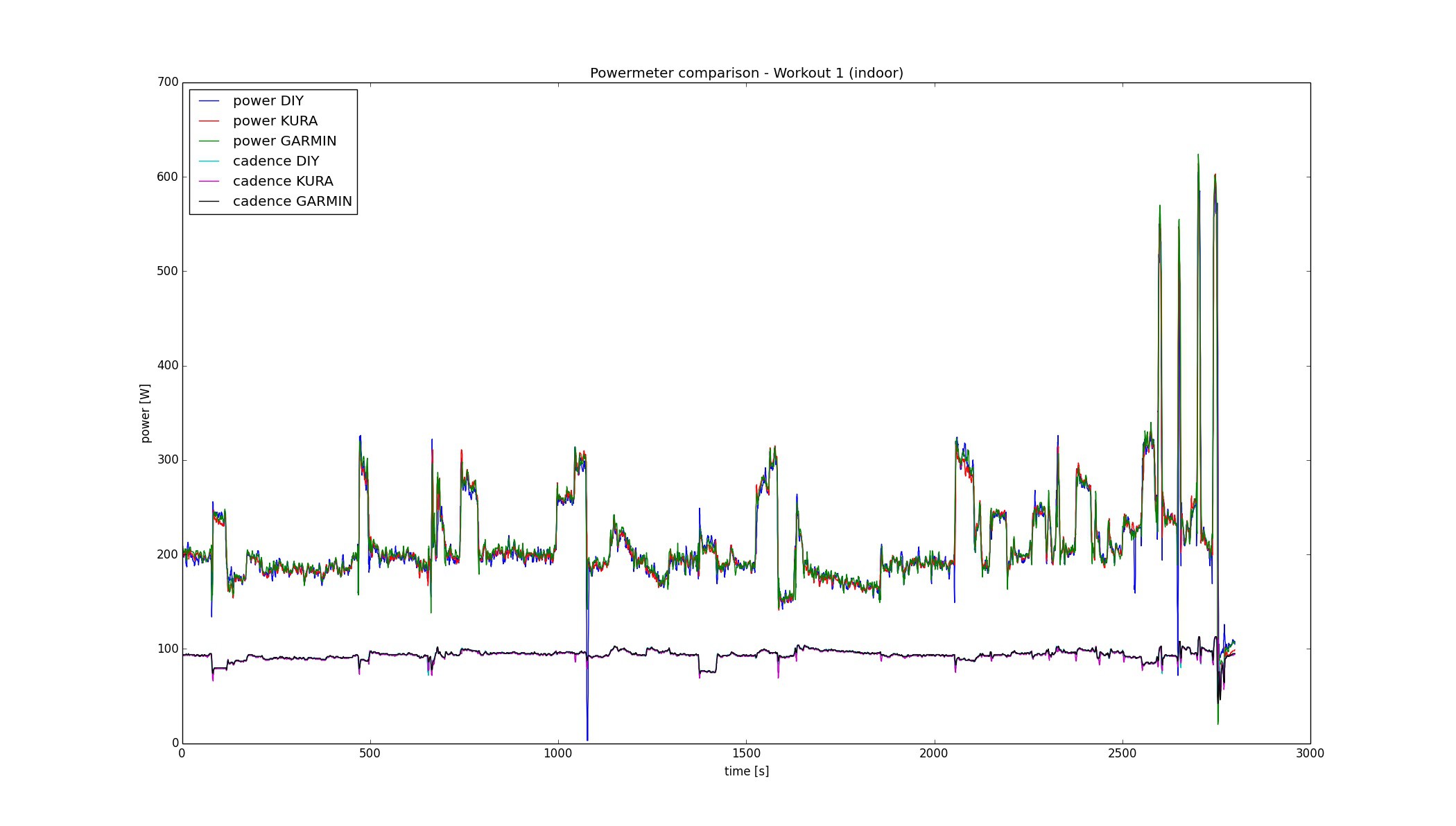
    First test ride is done. Ok, this one was easy, indoors on smart trainer, no changing weather conditions. I compared the output of my DIY power meter with the outputs of my Elite Kura smart trainer (claimed to be 1% accurate) as well as Garmin Vector 2s. 

    I am quite confident that I am on the right track. This plot shows the raw ANT+ data, no smoothing applied:

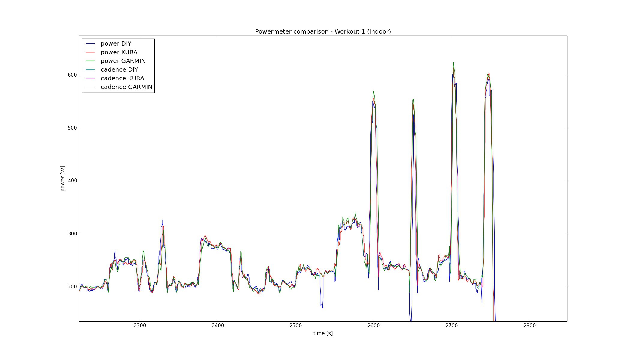
    Even short "sprints" are managed quite well:

    But will this work outdoors? Currently, we have like -3° C outdoors, so it will be a difference of 25° C between the warm crank at start and freezed crank at the end of the ride. We will see...

View all 2 project logs

Enjoy this project?

Share

Discussions

UltraReidar wrote 05/11/2021 at 20:37 point

Going to make one myself, if someone is interested

  Are you sure? yes | no

Jan Mares wrote 05/31/2021 at 07:10 point

Hi, I am really curious and also trying to do it myself. Sadly I have no experience with electronics so I am trying to learn the basics first.

  Are you sure? yes | no

Meerens wrote 03/24/2024 at 17:16 point

Late replay but how did it go can you present inside on the process?

  Are you sure? yes | no

holger wrote 11/07/2020 at 09:50 point

Great project! Do you provide the code somewhere?

Or can I buy the module or 3d-printed houses from you or somewhere?

  Are you sure? yes | no

afjnma wrote 09/27/2020 at 04:22 point

Buongiorno, mi piacerebbe costruire e studiare questo tipo d imisurazione e protocollo ant, è possibile condividere i codici?

  Are you sure? yes | no

Andreas wrote 09/16/2020 at 12:32 point

Great project! Would you like to tell me which DMP components do you use as measurement bridge?

  Are you sure? yes | no

khani3s wrote 06/20/2020 at 22:07 point

Could you explain more about your strain gauge setup/orientation? Awesome project!

  Are you sure? yes | no

Colum wrote 04/12/2020 at 22:29 point

Any update on this project! Want to build one myself!

  Are you sure? yes | no

Eurico Jardim wrote 08/15/2019 at 18:01 point

Congrats for your powermeter 🙌 ... I would like to do the same! Could you share more info (maybe code, libs)? What about the battery? Thank you for you idea share... TOP PROJECT

  Are you sure? yes | no

Loic Sanschagrin-Thouin wrote 07/07/2019 at 13:55 point

I think your project is very cool. 

Just by curiosity, how exactly does your algorithm works to measure the torque during a rotating cycle ? I mean they are some moments when a cyclist pedals that the force is lower than other moments. Do you select the greatest value your sensor reads every second ? 

Thanks for your reply !

  Are you sure? yes | no

T.Burns wrote 05/17/2019 at 09:08 point

So the question is can I have the plans for this to build it myself?

  Are you sure? yes | no

simone.mirco wrote 11/08/2018 at 17:27 point

I find your project very interesting. Is there any update?

  Are you sure? yes | no

bearmos wrote 03/22/2018 at 12:00 point

also, check out the molex MX120G series headers for an inexpensive IP67 rectangular connector (they're probably too big). They would provide a nice robust watertight connection (a concern once you get this out into the weather).

https://www.digikey.com/product-detail/en/molex-llc/0367831201/WM9330-ND/3661543

https://www.digikey.com/product-detail/en/molex-llc/0367921201/WM9332-ND/3661542

You could also design in an o-ring gland, but that's probably a bit more challenging than spec'ing a water tight connector, since it would have to be kept sealed.

  Are you sure? yes | no

rock-o-mat wrote 03/22/2018 at 17:06 point

Yes, this is too big. The thickest part of my power meter is 12mm, the current 2 row connector is only 5mm. I think that I can drop the debug pins in future designs making it a 1 row connector, but still it needs to be really thin. There is not much space between crank and frame.

  Are you sure? yes | no

bearmos wrote 03/22/2018 at 11:48 point

Looks really promising!  If you run into issues with temperature drift from the HX711, you could try an LMP90100 (gain stability is 0.5 ppm/degC) which is an order of magnitude more stable than the HX711, and the raw IC is also able to be sourced directly (I can only find the HX711 from sparkfun)

  Are you sure? yes | no

rock-o-mat wrote 03/22/2018 at 17:15 point

Temperature drift might be an issue on HX711. But it is cheap and easy to get here in europe. Thus, I will try to deal with temperature variations in software. If this is not going to work, I will switch to a different ADC. So thank you for pointing me to the LMP90100. 

  Are you sure? yes | no

Similar Projects

Does this project spark your interest?

Become a member to follow this project and never miss any updates