Close
0%
0%

Sweet Dreams CNC (multimachine)

There are solutions and there are elegant solutions.

Similar projects worth following
Shed built 1m cube CNC / multimachine. Short levers and a different rigid frame design, plus modular mount allowing anything from pick and place head to burner for custom toast... Thanks for your interest in this project.

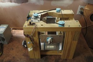
I started designing this 200kg beast in 2010, 2 years and 900+ revisions later and it was ready to decide if it would make it into the real world.

Unfortunately, this coincided with a couple of business trips to China... so the first constraint was no longer that it had to fit through a standard doorway, but what's the longest profiled rail I can get into my luggage?

Fast forward to boxing day 2012, the frame is built, painted, but not a whiff of electrical progress or cable. Meanwhile a friend who had been helping out with some milling of the Z axis had mentioned the project at his local model engineering club who in turn had a stand at the prestigious Model Engineering Exhibition at Alexander Palace in London. It had been suggested that I turn up with the CNC and ruffle the feathers at the showcase of real model engineering. :-) Anyway, back to Boxing day. I ring my buddy and ask what are the dates for the show, March wasn't it?
er, no, comes the reply, January 12th; (It probably wasn't the 12th but I didn't hear anything after JANUARY!)

  • 1 × 20mm hiwin profiled rail
  • 1 × SKF ball screws
  • 5 × Kinco 2M880N. 8 amp drivers 5? yep, hot swap built into the design. In the event of one dying, move some cables and up and running again!
  • 4 × steppers, nothing special, low impedance SY60 NEMA 34 types.
  • 1 × Huangyang 3hp 24k rpm water cooled spindle

View all 17 components

  • The table lore

    Crum3le09/28/2015 at 11:52 0 comments

    The table also needed to be solid, 40mm box section thick wall (as in the pic) in asymetric positions. About 70kgs. For heavy work, the 3 pieces at the right of the pic, plenty of room for clamps and the gaps for mounting larger pieces vertically if required. the tubes are welded onto some angle in an offset arrangement. This gives about 50mm difference in height when the bed is flipped over. its located into the frame with dowls and 10mm bolts. 4 bolts allow the table to be removed completely and a different table can be mounted. 4th axis or coolant catcher type. The sides of the CNC are open, allowing work to be slid across the table not limiting the size of the workpiece to the width of the CNC. A sacrifical bed was fitted made from some form of compressed recycled plastic and resin (I dont know what its called but its temperature stable, oil and waterproof)

  • The suicide test episode.

    Crum3le09/26/2015 at 19:53 0 comments

    The suicide test;

    So the machine has progressed past turning it on without any magic smoke pouring forth, all the bells are ringing and the whistles whistling.. (why don't bells belling?) spindle has been powered up and a couple of small tests run. But I'm still air cutting at this point. ...The commissioning continues.

    Time to up the ante.

    Bearing in mind that body parts may well be found in the same vicinity as gantries and other moving parts, cue the Suicide Test.

    For the benefit of the casual CNC visitor, The suicide test is conducted as follows;
    1. Set gantry at one end of the X axis.
    2. Set speed in excess of 30 metres per minute.
    3. Hold down the button and drive the gantry at the highest speed you can get into the stops at the other end of the X axis!

    4. Wait for the very loud bang.

    5. Repair as required.


    I hit the switch and even though I knew what was coming, there was a whirr and a blur as the gantry shot from one end to the other faster than my eye could follow. There wasn't time to take my finger off the button before the limit switches did their job. I don't have an exact figure of the speed it reached but I can tell you that the gantry was still accelerating when it crashed into the the Omcron microswitches at the far end of the profiled rail.

    There's 10mm of switch protruding from the box section upright. These particular switches have 3mm of movement, .1mm between open and closed. The speed of the gantry when it hit the switch can be calculated from the time taken between the switch being activated and the distance traveled before stopping. The speed of light and the price of fish being unequal, the gantry was travelling in excess of a "greased lightning" when it got to where it was going!

    Confidence went much higher after that test. The limit switches worked great, even in the worst case scenario of a runaway gantry, the worst that I'd expect to see was a crushed switch as the gantry didn't get as far as hitting the metal frame uprights which would have been an interesting end to the frame, and X axis drivetrain.

    If you are building a machine, fit the limits and E-stops before you wire the motors. Watching a gantry move at high speed is really not something you want to see from the wrong place. If your gantry moves as quick as this one did, you'll never make it to the power switch in time.

  • Background and design spec evolution

    Crum3le09/24/2015 at 13:30 0 comments

    Background and design spec.

    I'd seen a lot of CNC builds where the second one was just used to remedy the faults of the first one. That wasn't going to happen to me ! lol... So in this section I'll try and explain some of the decisions I took and why. I should also add that at this time, not only did I not have all the answers, I didn't even have some of the questions!

    Although I had a good idea of what I wanted to achieve and some ideas I'd not seen used before that I thought would improve the build or make it easier. This CNC was not going to be an exercise in what was theoretically possible, just a no frills, very VERY strong, quick and easy to build structure that a tank could drive over! It had to be built without recourse to another CNC or exotic measuring equipment, just the equipment I had, could borrow or was prepared to buy. I did have some milling done on the frame, (making the 26x 22mm holes for the conduits, we had a jig on the mill and just knocked them out but that could as easily have been done with a pillar drill but would have taken a lot longer. Apart from that milling job, it was built with power tools and a pillar drill.

    It seems like a long time ago I asked the question "what do I want to cut with it?" "Don't know yet" was the unhelpful conclusion as I recall. But after much thought about what I needed, opposed to what I wanted. I came up with a basic spec; a very strong, fast CNC that could work anything I threw at it including metals and portable enough to fit through a standard door. The ability to use the addressable 3d space with other implements was also seen as a bonus.

    Design criteria (draft 5)
    A few additional criteria added during the build, the spec mainly stayed the same and was met.

    1. Portability; Self contained, Electronics contained within the design, able to fit in the back of the car / through a doorway.

    Overall, successful. although a hydraulic trolley, lifting jig and 2 people are required to move it. it can be moved by one person but its a swine. It fits into the back of my car and would go through a doorway. It is also capable of creating its own doorways if required.

    2. Able to handle any material I was likely to throw at it. With the best accuracy I could build in a shed.

    Successful. (Probably... really need to fit the slower motor to test it with SS.)

    I couldn't see me needing to work anything harder than stainless steel, so that was where the bar was set. The easy part of the design was discarding wood and alloy extrusion for the build. Converting an existing mill was explored and discounted. So, metal was going to be the material, box section would give me strength to weight advantages as well as simplify the construction process.

    2a. Strong and rigid, lots of rigid.

    I realised fairly early on that for the performance I was wanting, a hybrid of bolted and welded steel construction and profiled rail were the right option. So large quantities of 80mm thick wall box section steel were calculated. The Hiwin catalog and price lists took a beating too.

    I looked at various existing designs but was also aware of the limitations they created. There was a lot of sketchup time invested in looking for the solution and one variation kept winning over others, one I'd not seen before. The description sounds harder than it is so bear with it. A box made of box section wrapped around another box made of box section wrapped around another box (made of 20mm alloy plate). That describes the X, Y and Z axis.

    While getting a rigid frame was IMHO critical, getting all the levers as short as possible was just as important. More hours and iterations invested doing that..

    I also spent a lot of time getting the loads generated by the milling process contained within the bearing footprint. So the spindle works inside the Z axis bearing locations, the whole of the Z sits inside the Y etc. (as an aside, this can limit the vertical travel you can get from the spindle - if you want it to remain inside the footprint, so...

    Read more »

View all 3 project logs

  • 1
    Step 1

    Some unsolicited but practical advice if you are thinking of designing and building your own CNC;

    You wont know all the answers before you start, you wont even know all the questions. Start anyway it'll be the most satisfying thing you ever build.

    Just say no. Stay at home and set fire to £20 notes. It'll be a lot cheaper, less stressful and more enjoyable.

    Your experience will be somewhere between those two axioms and probably encompass both.

View all instructions

Enjoy this project?

Share

Discussions

Crum3le wrote 09/26/2015 at 16:20 point

Thanks for your interest and for looking at this project.  At the shows where I've taken it to demo, one of the questions asked is how accurate is it? Well, according to the spreadsheet its good for 5 microns and that's tool tip deflection.  :-)  I've no way of measuring 5 microns and I dont know that the CNC has read and understood the spreadsheet. However, it's certainly capable of getting to any accuracy I've needed so far.   Lithophanes look very crisp from it.

  Are you sure? yes | no

Similar Projects

Does this project spark your interest?

Become a member to follow this project and never miss any updates