0%
0%
IoT Matrix Word Clock
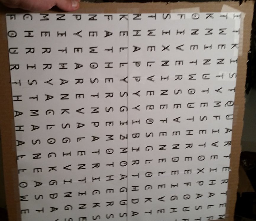
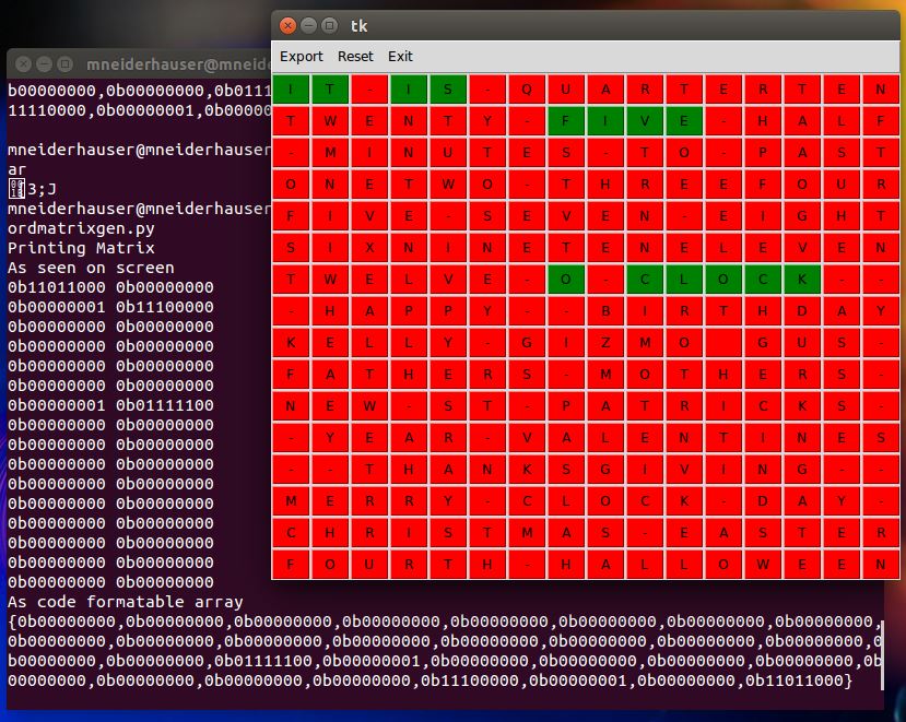
The creation of a web connected clock that uses a character matrix (words) to display time.
 mikeneiderhauser
Become a Hackaday.io member
Already have an account? Log in.
Just one more thing
To make the experience fit your profile, pick a username and tell us what interests you.
Pick an awesome username
hackaday.io/
Your profile's URL: hackaday.io/username. Max 25 alphanumeric characters.
Pick a few interests
Projects that share your interests
People that share your interests


 Circle Electronic
 deʃhipu
 davedarko
oops, sorry, I meant to post the KS url: www.kickstarter.com/projects/252714519/clockfour-chronogram-a-full-color-word-clock
& this is their website: http://wyolum.com/
they still appear to be selling the 'clockTHREE Jr' (23cm x 23cm) via Seeed, but the clcockFOUR Kickstarter was to be 28cm x 28cm, & RGB LEDs.