 Jan
JanUpdate 02.06.18
I had @Graham Murphy 's comment stuck in my head all the time and by coincidence I stumbled upon a video by Dave jones:
This seems to be exactly the case with my flawed "design". @ the 5 minute mark he's doing excatly what I did in my circuit. The µC is connected to VCC by RST via a ~10K pullup. This alone doesn't provide enough power. But by having other IO's connected to VCC the µC starts working.
Amazing stuff. Video is absolutely worth watching!!!
Hey guys, I need your advice!
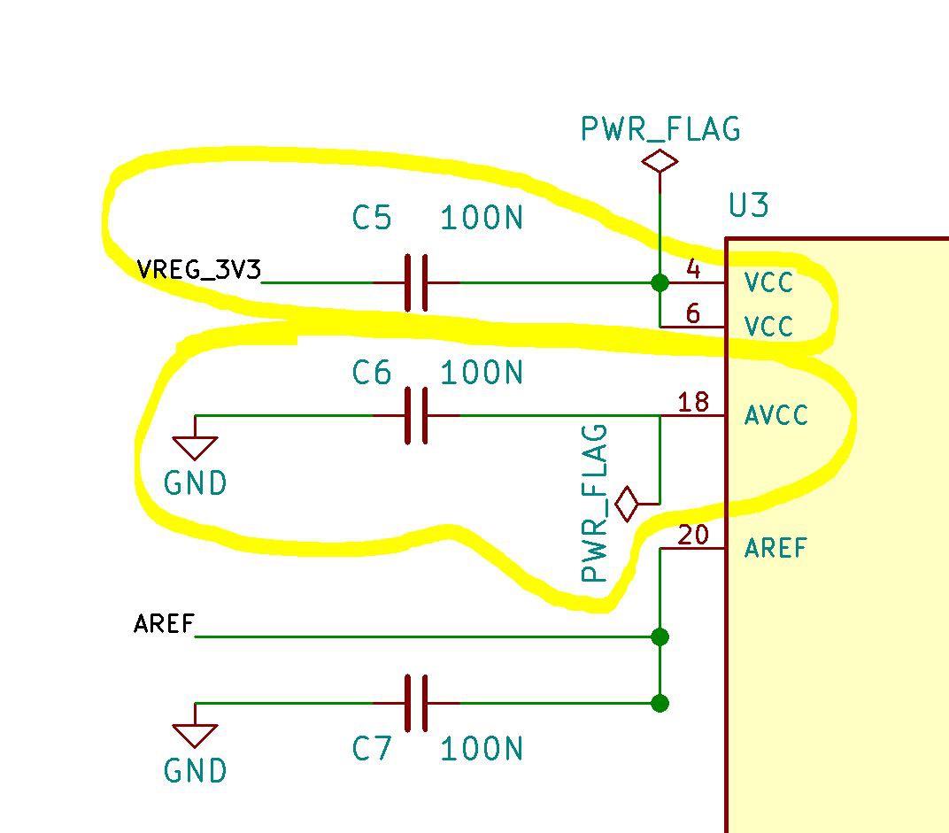
Look, I already made the huge mistake to not connect AVCC to VCC but only to GND via cap C6. So I soldered a wire from AVCC to VCC to fix that.
BUT guess what! I did another really stupid thing. I connected both VCC pins of the Atmega328 to 3V3 with a cap in between (C5). My brain hurts now as there should be no current flowing in an DC circuit right?
Why does to whole thing work after all???
My only idea is that the Atmega is able to run even if only AVCC is connected to 3V3 because it's internally connected to the other two VCC pins?!
Discussions
Become a Hackaday.io Member
Create an account to leave a comment. Already have an account? Log In.
Possibly because each I/O pin has a set of diodes that go to both VCC and ground. Applying voltage to the I/O pin could result in that being routed to VCC.
Are you sure? yes | no
Hi Graham, thanks for you input. I'll def. look into that! A quick search in the datasheet didn't bring out much yet.
So I have to dive deeper into the chips internals to understand why my design works!
Are you sure? yes | no
see update: You were absolutely right!
Thanks :)
Are you sure? yes | no