 Alex Rich
Since my dog ate the remote, I figured it would be cool to design a new housing for it. The new housing will be 3d printed and can include any custom features I want. The first step, however, is to just recreate the original remote enclosure as accurately as possible. One of the trickiest parts is getting the silicone button pad on the original to match with the new remote. Below are the steps I took to (hopefully) match the button pad fairly closely:
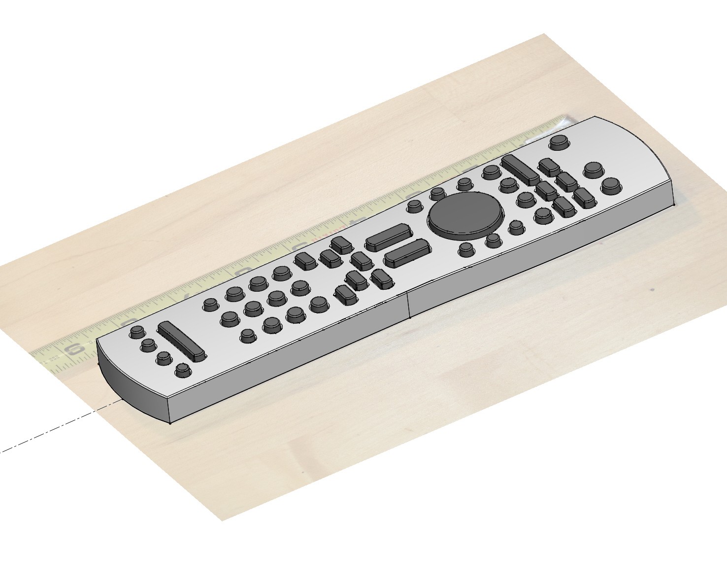
1) I took a picture that was as "straight on" as possible to capture the button locations. To remove most of the perspective effects, I mounted my camera to a ceiling joist in my unfinished utility room. Then I zoomed in on the remote.
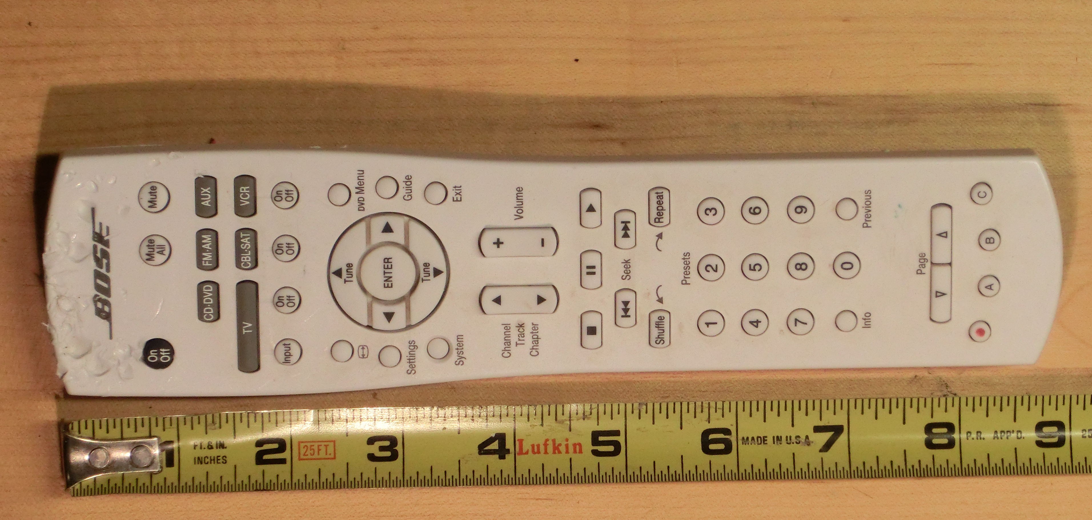
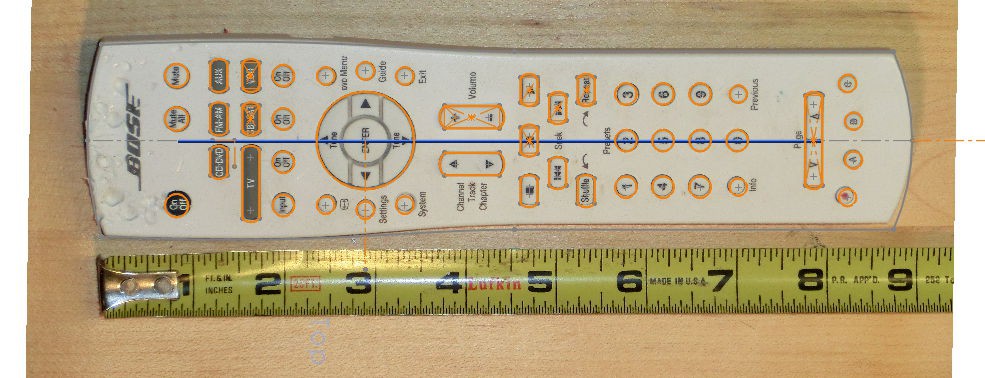
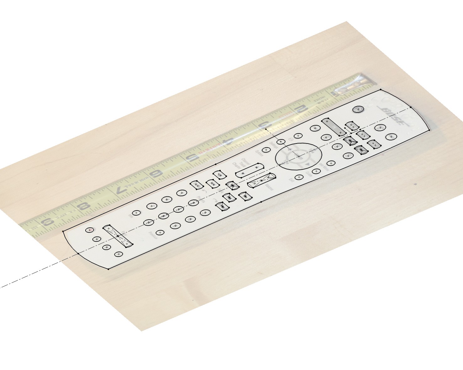
2) I pulled the picture into CAD (Solidworks in this case because I'm faster with it, but you can also do this in Onshape for free) and scaled the image according to the tape measure in the picture. After this it was a matter of sketching the buttons on top of the picture.
3) After this I sketched the remote outline and then printed the sketch to scale on paper. This let me compare my sketch with the real remote using a lightbox, but you could also just hold it up to a light to get a decent idea.
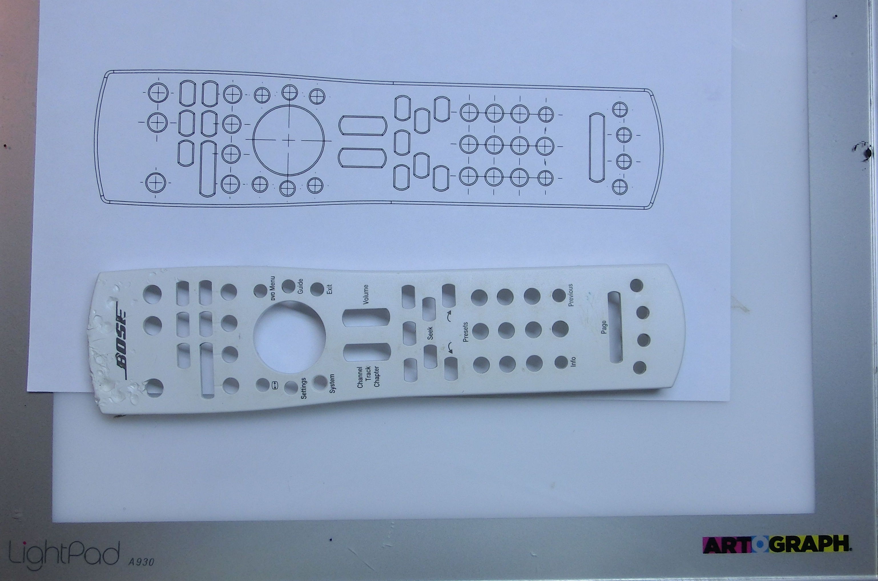
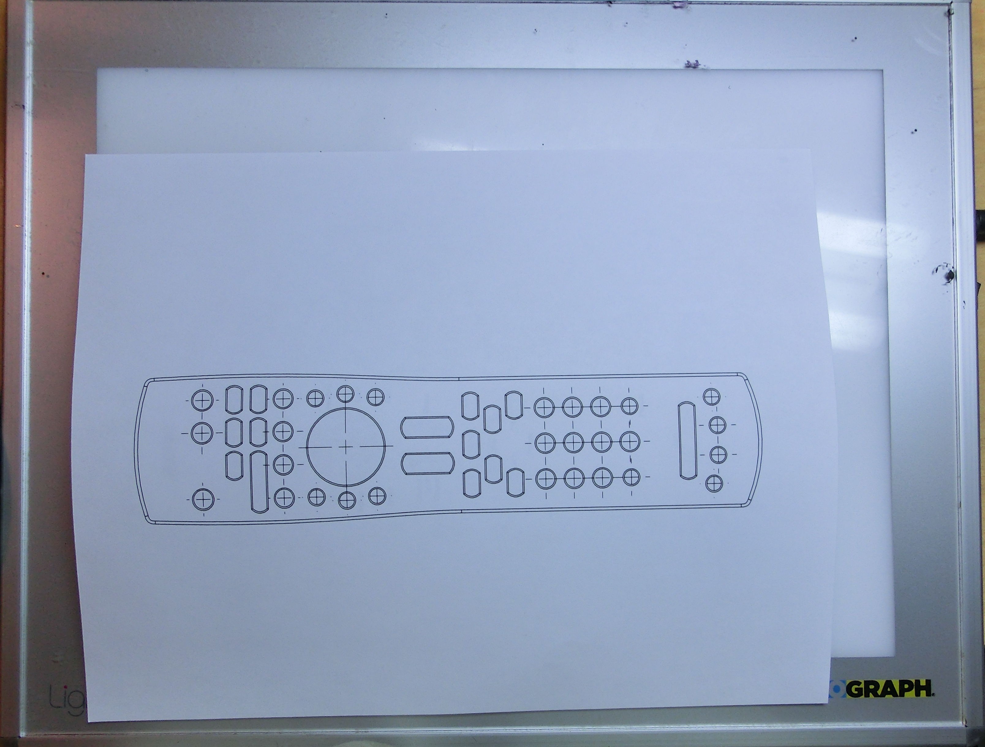
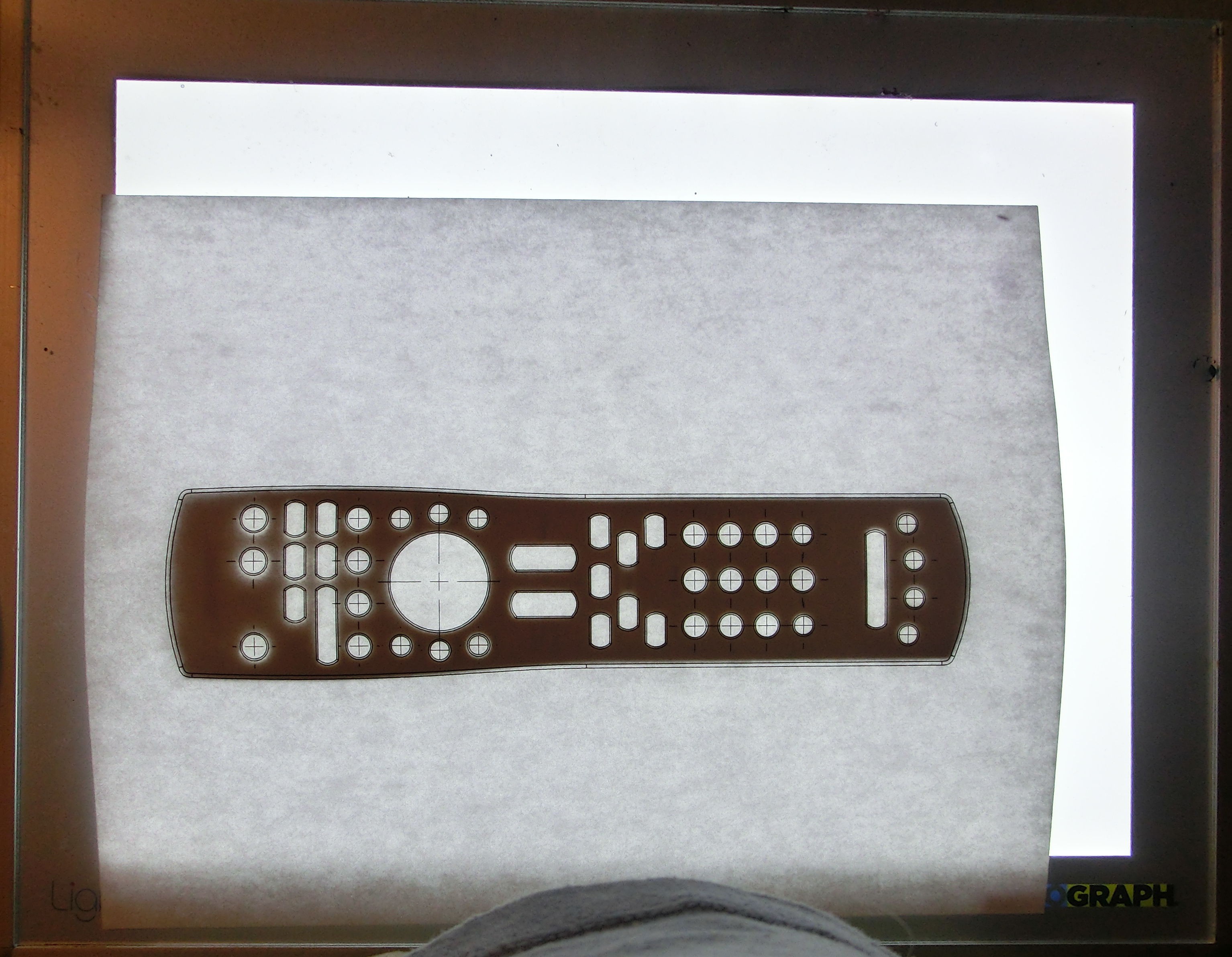
It took me several tries to get this right, despite having the tape measure in my picture I had to scale and iterate about 3-4 times to get it to look like the picture above.
4) Now that I know the buttons on the old remote will align reasonably well, I am moving forward finishing the enclosure design. Below are a few pictures of that process:
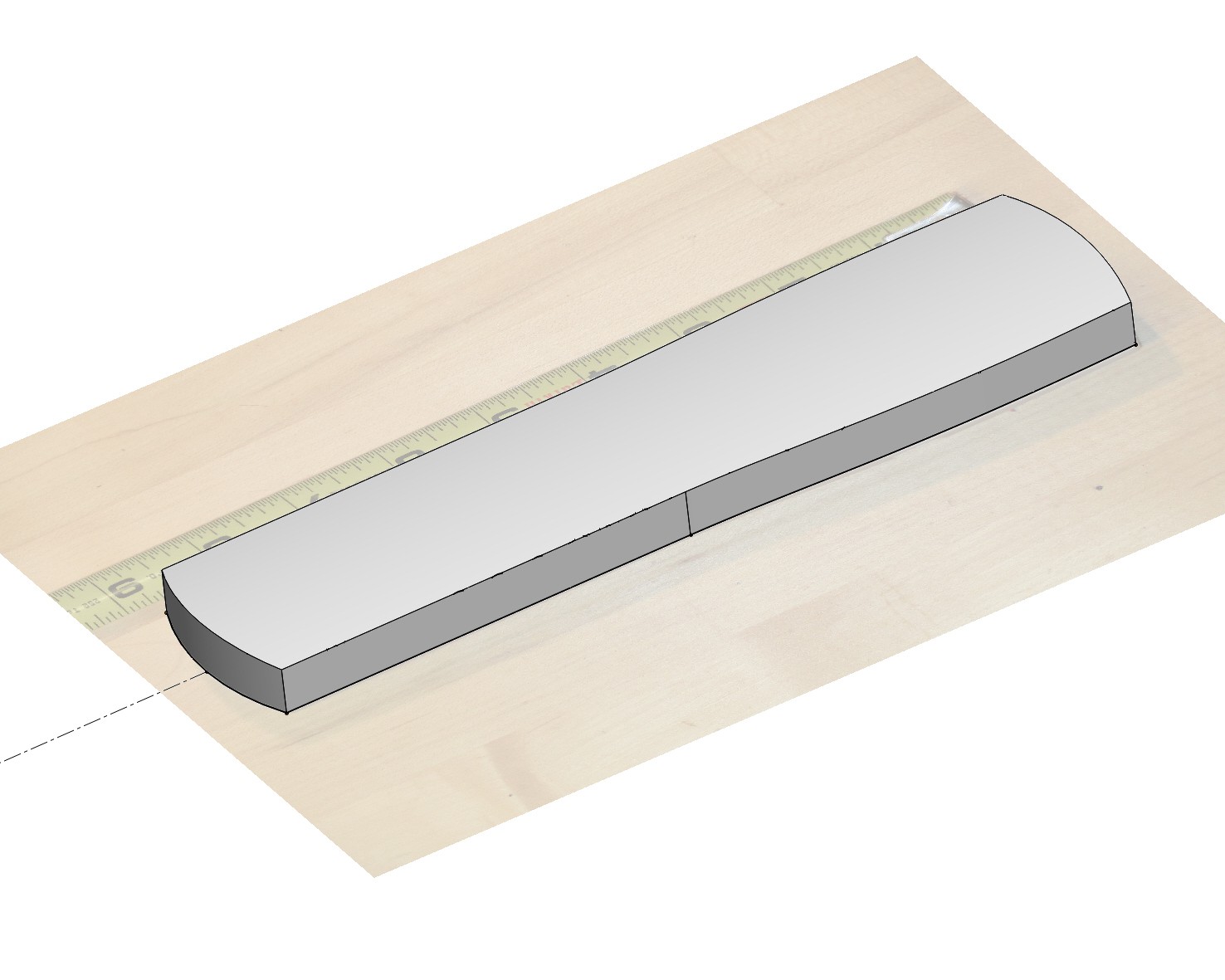
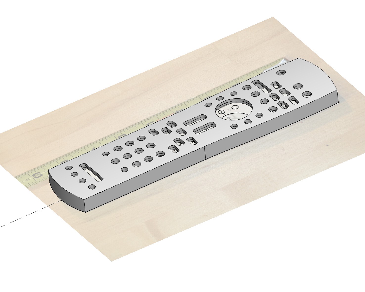
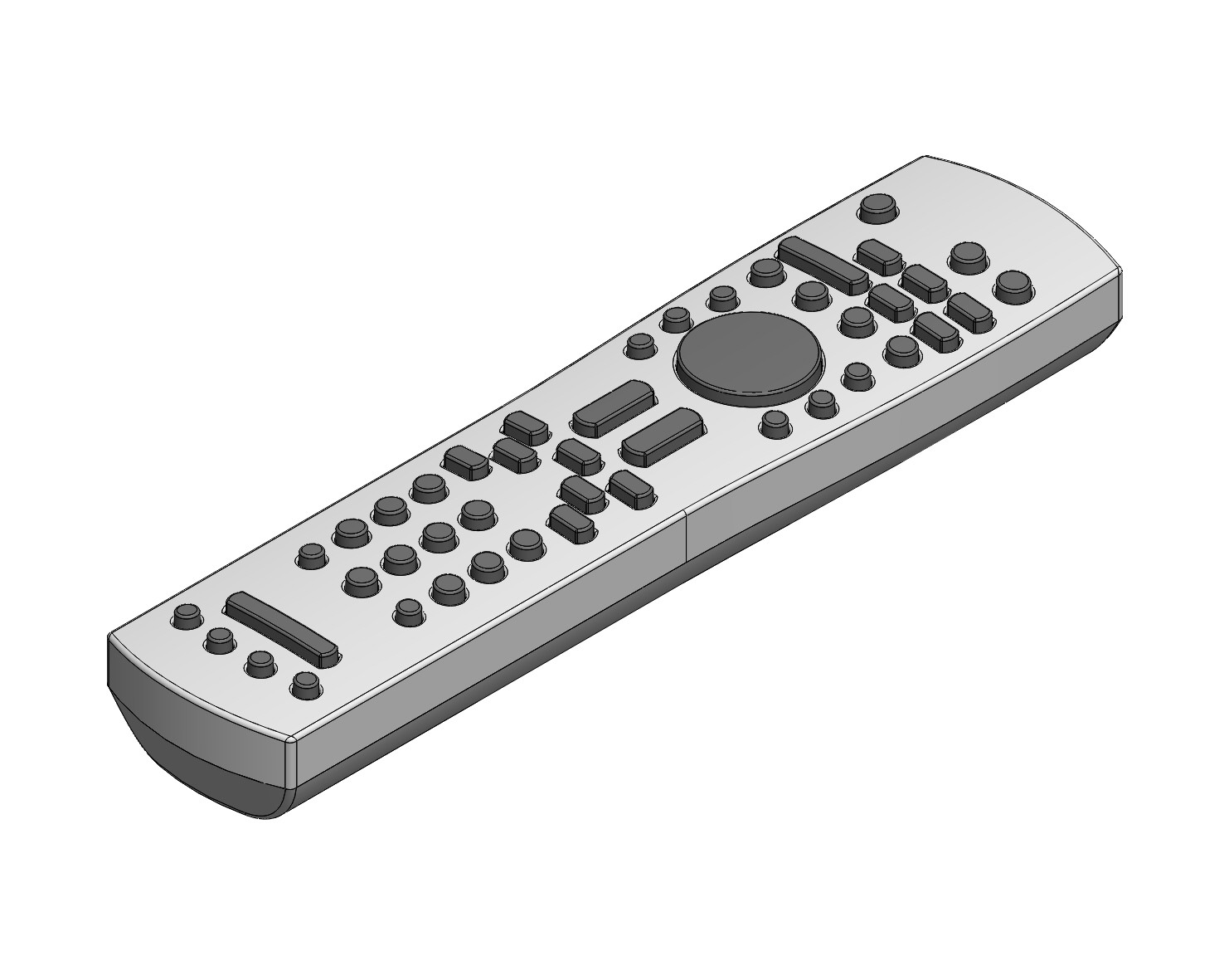
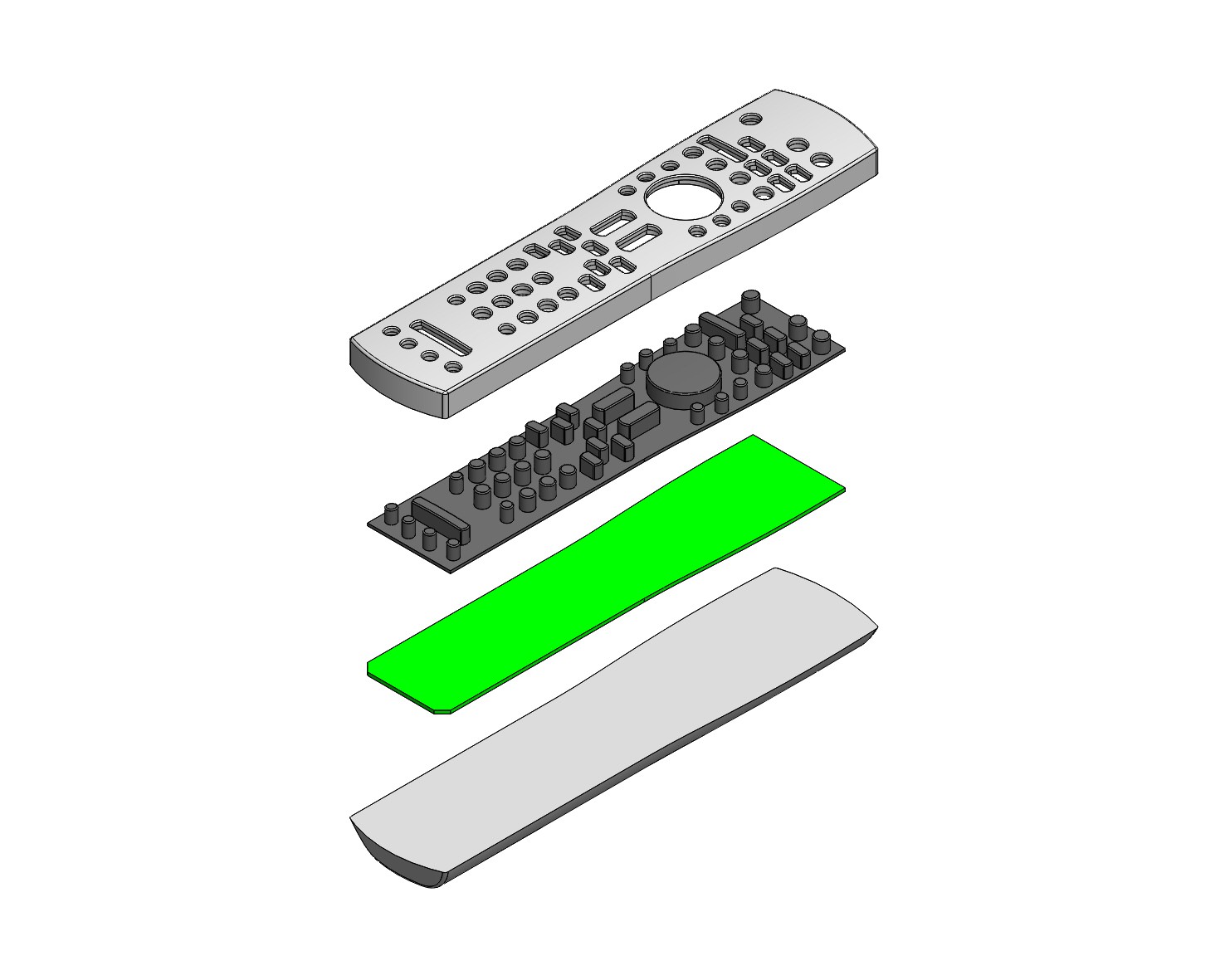
Need to finish the back of the remote including battery compartment and my replica of the original remote should be finished. Then I can decide if I want any extra custom features before 3D printing.
Discussions
Become a Hackaday.io Member
Create an account to leave a comment. Already have an account? Log In.