 Alex Rich
In this log I'm going to show the process I used in CAD to finish up the enclosure for the remote. This involves taking the blank enclosure shape and adding a cavity, a battery compartment, battery door, supports for the PCB, bosses to connect the enclosure halves together, and anti-wobble nubs.
CAD can seem daunting but really it involves a series of simple steps that can result in something fairly complex. I am going to try to walk through the steps to remove some of the mystery from the process. See previous logs for how I did the main enclosure design as well as the button pad on the other half of the enclosure.
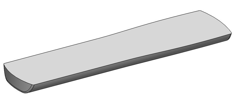
Starting point:
Final result:
CAD STEPS
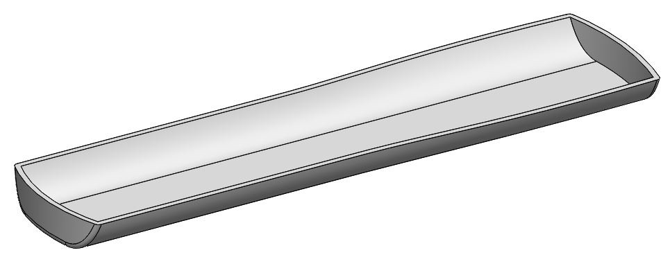
1. Shell
Using a shell command, I take the solid enclosure model and create a cavity with constant 2mm wall thickness in all places. Shell is one of those commands that most CAD programs have. It should also be noted that the shell command likes simple smooth surfaces, if you try to shell something with too many funky shapes it will most likely fail, so it is best to shell early on in a design.
2. Battery compartment
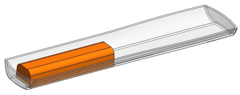
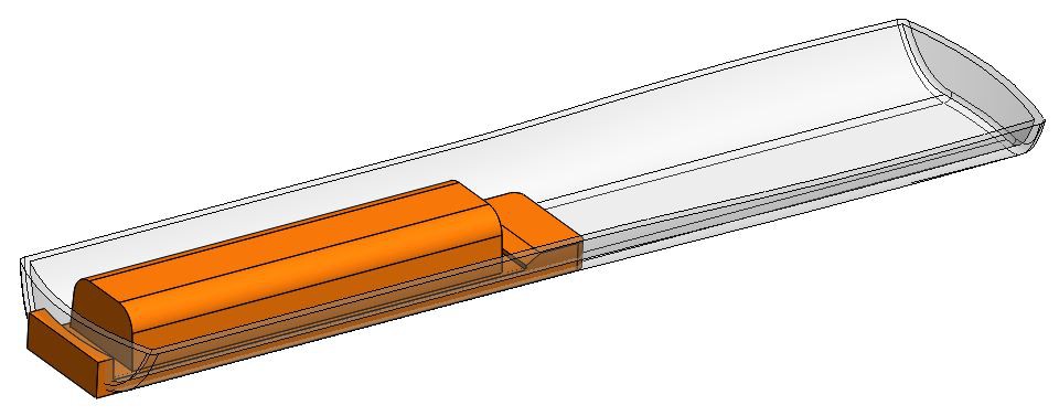
The battery compartment will be indented into the main enclosure shape and will have a 2mm wall thickness around it as well. Below in orange I have begun to model the "air" in my battery compartment. The orange piece is a separate body that is not physically merged to the main enclosure.
Below you can see I have added additional detail to the orange body, these details will be indented into the main enclosure.
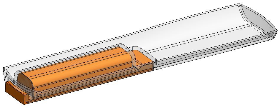
Hopefully the below picture shows clearly what happened, the orange body was used as an indent tool on the main enclosure. There is definitely more than one way to achieve this result, I have always liked using an indent because it is more versatile if I ever want to go back and make changes I can just roll back and change the orange part and the indent will automatically update.
After indent is done the orange part is no longer used and can be hidden or deleted. Below is the result with the enclosure shown as opaque rather than transparent.
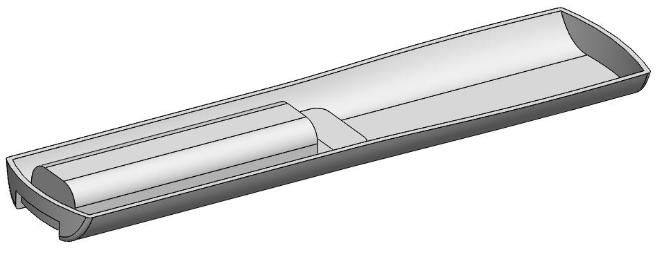 another view
Next I created several cuts for the battery springs on the PCB to fit through the battery compartment. I also cut away an area for the battery door latch to clip in (upper right of the battery compartment). Before the cuts I added support ribs for the PCB, making sure they are in areas where there are no components. The purpose of these ribs is to add support to the PCB to prevent the board from flexing too much when buttons are pressed on the remote.
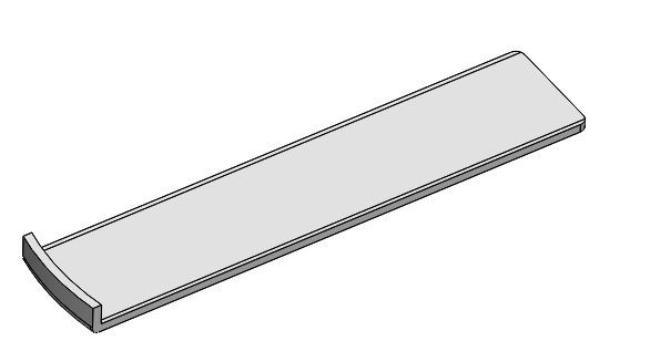
3. Creating the battery door
The battery door will follow the same shape as the enclosure before the battery compartment was indented. To get this geometry back I rolled the design back to just before we created the indent, after the shell command. Then I made a copy of this body:
 From here I cut away everything except the portion that will fit in the battery compartment. This was done by offsetting the edges of the battery compartment opening on the main enclosure by 0.01" to cut away the door plus a little clearance. 0.01" is a good clearance for 3D printed parts that you want to slide smoothly, if you go tighter than this you will probably end up sanding to get things to fit.
 Next I added snaps so the battery door will click into place in the battery compartment:
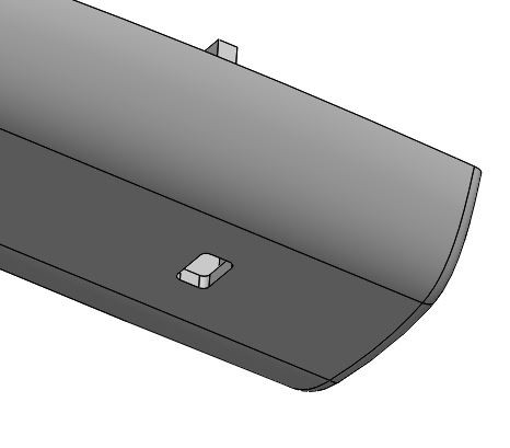
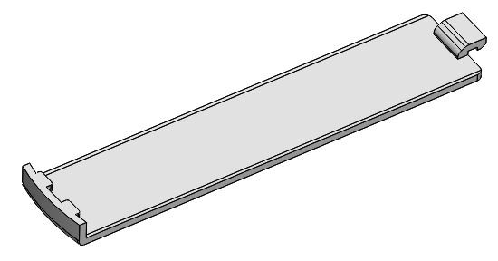 Finally I added a little indent to indicate where you press with your thumb to open the battery door:
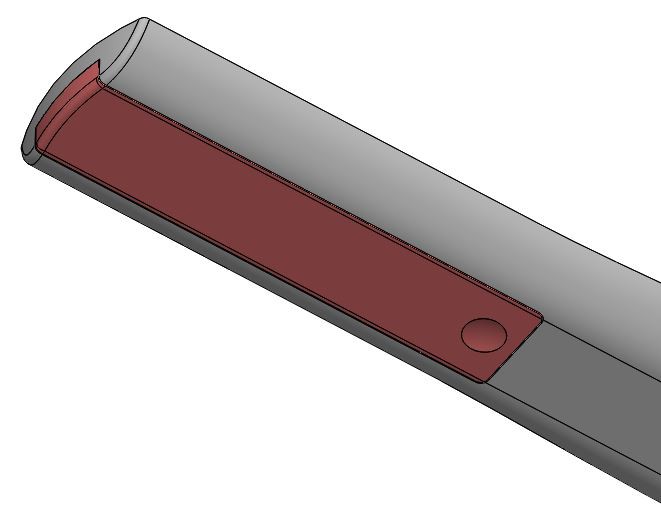 Below is the door shown through the transparent enclosure:
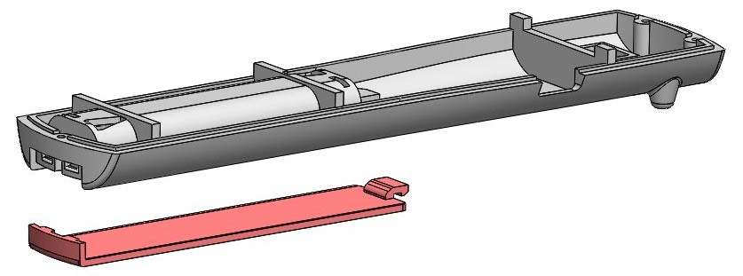
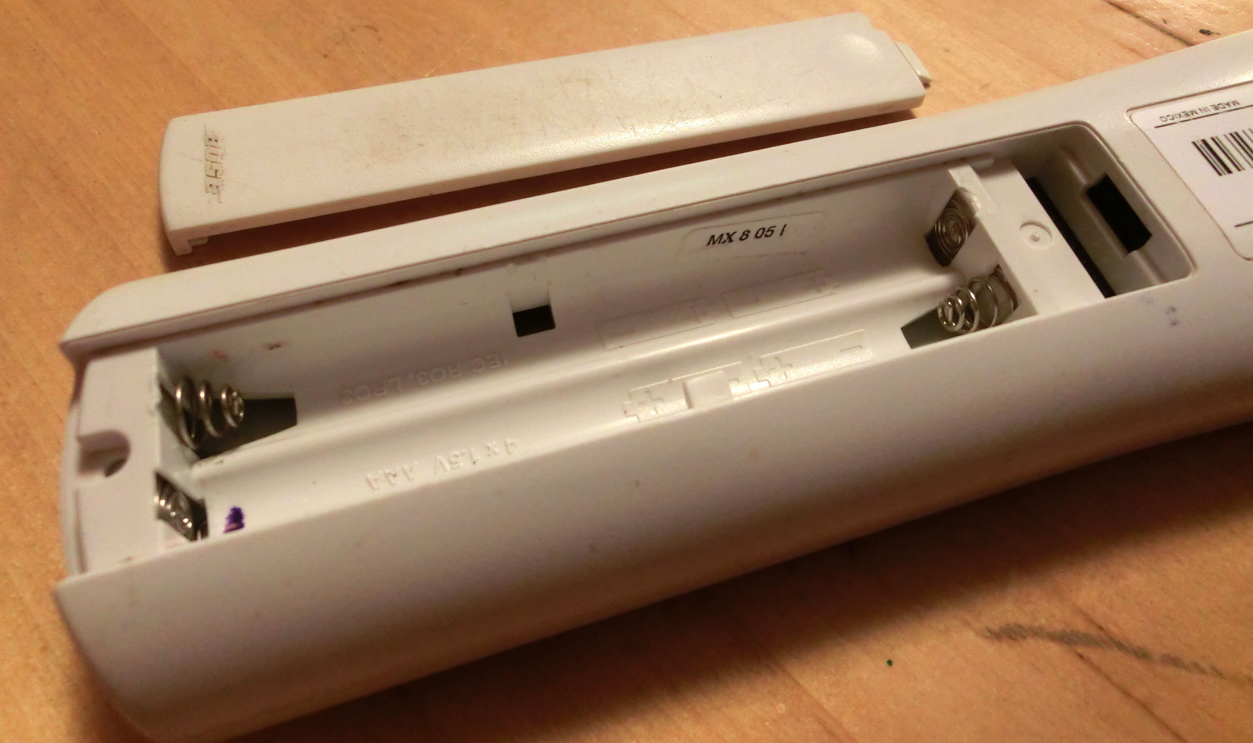
 Here are the real parts I have just recreated. Obviously the real remote enclosure has a few more details, I have intentionally simplified for this design.
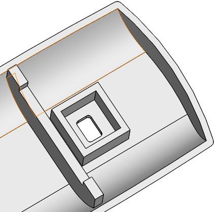
4. Slider switch mounting
I want to have a hard off switch for the electronics I am adding to the remote. This minimizes battery drain when I'm not using the auto volume control. For this I am using a sliding switch I had laying around, it will fit in a small box in the enclosure with a slot for the sliding switch to protrude out of the enclosure. This is not a panel mount switch so I will hold it in with a little bit of hot glue, fine for this application.
![]()
![]() 5. Anti wobble nubs
5. Anti wobble nubs
 5. Anti wobble nubs
These little nubs are on the real Bose remote, and are a good idea because the allow the remote to sit flat on a table without wobbling. In my case the nubs will also keep the slider switch from directly hitting the table when you put the remote down.
I tried not to overthink these - just tapered cylinders up-to the enclosure.
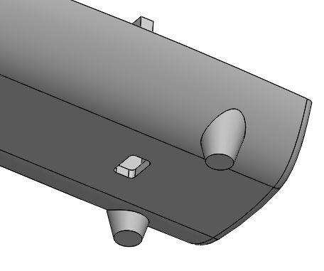 And simple fillets to round the nubs:
![]() 6. USB port opening
6. USB port opening
 6. USB port opening
I had to cut this opening in the side of the real Bose remote for reprogramming the Trinket. Since I am designing from scratch I am just going to add it ahead of time.
![]() 7. Screw bosses
7. Screw bosses
 7. Screw bosses
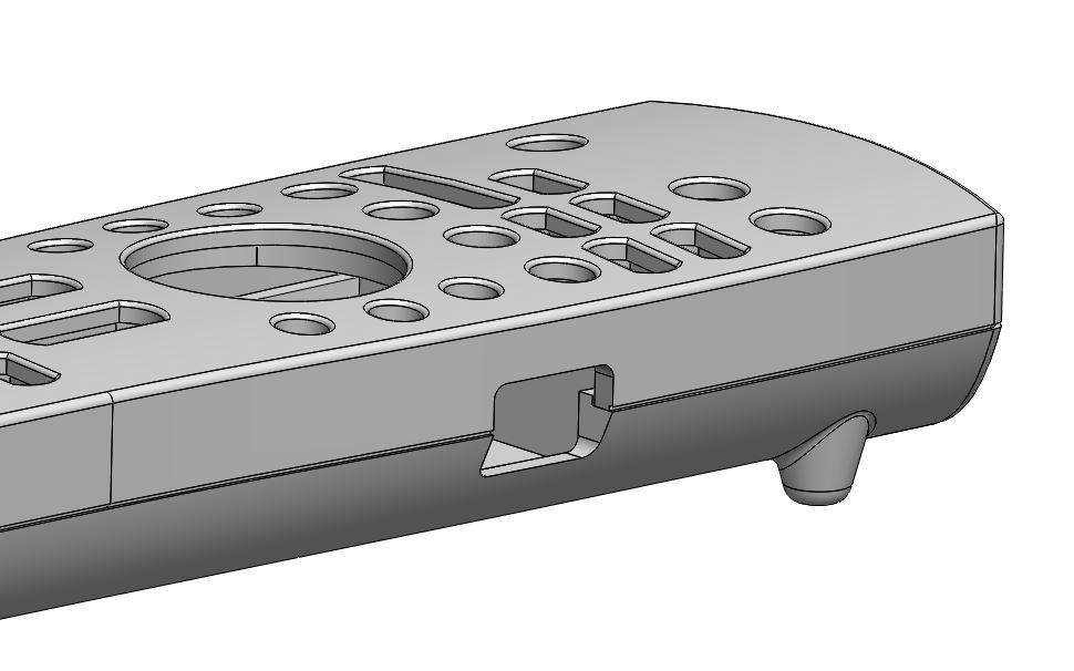
I added bosses for screws to attach the enclosure halves at the top and bottom. The back of the enclosure has bosses with counter bores and a clearance holes for No. 2 screws, the front of the enclosure has bosses with pilot holes that I can tap with a No. 2 thread.
 Cross section of the bosses:

8. Done
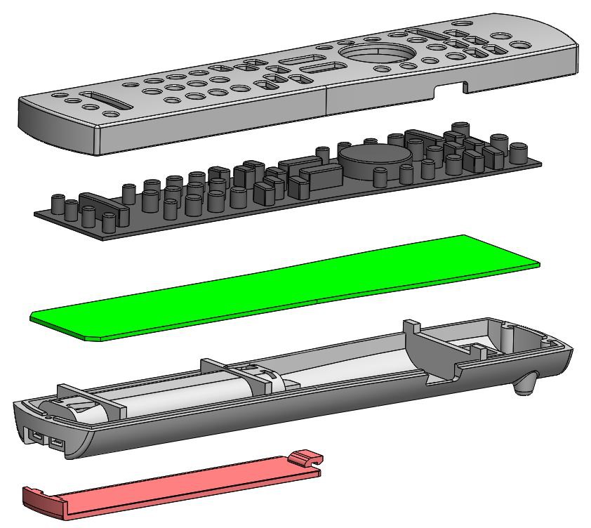
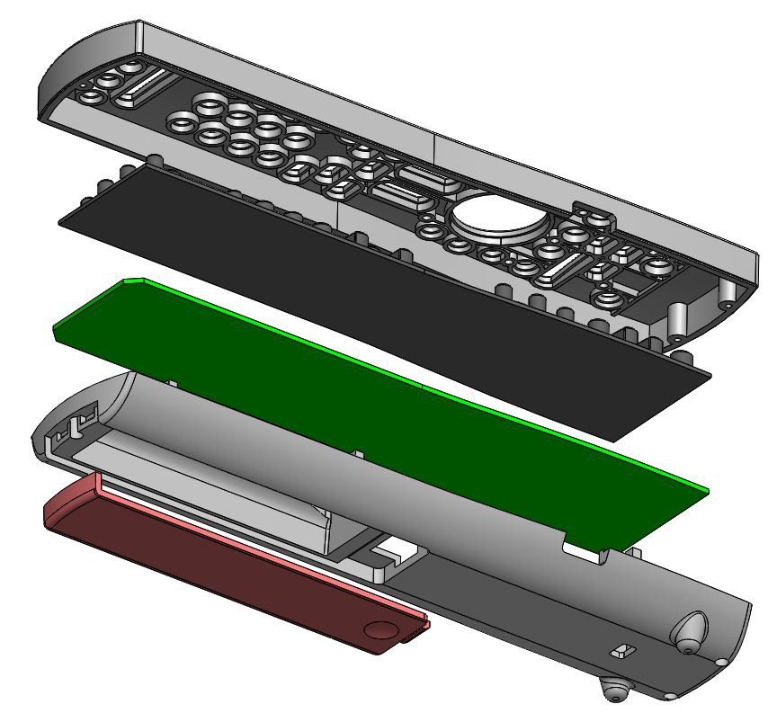
Here are a couple exploded views of the finished remote enclosure ready for 3d printing.
Discussions
Become a Hackaday.io Member
Create an account to leave a comment. Already have an account? Log In.