 AVR
AVRRepRap-XY-i2 development resumed a couple weeks ago! I'm happy to say I'm working on this thing again, I've been itching to get it finished for a while. Anyways I have spent the last few weeks printing out all the parts that remain unchanged from Jand's variant. While parts printed I remodeled a few parts of the printer, the Z axis, inner corner brackets, frame corner brackets and the spacer block pieces.
I'll start with the Z axis, originally the Z axis design consisted of many printed parts that clamp together around a M8 nut and clamp onto pieces bolted to the 2020 extrusion. The original design relied entirely on friction and clamping force to hold together the Z axis. I decided this was unacceptable and remodeled it to be 5 printed parts total instead of 9. The redesign is based around a central block type piece:
This part mounts an openbuilds nutplate for their 8mm leadscrew in the center, the 2020 exstrusion for the Z axis is bolted on the sides. The rest of the Z axis is just the LM12LUU clamp sides that are bolted onto the other sides of the 2020 extrusion:

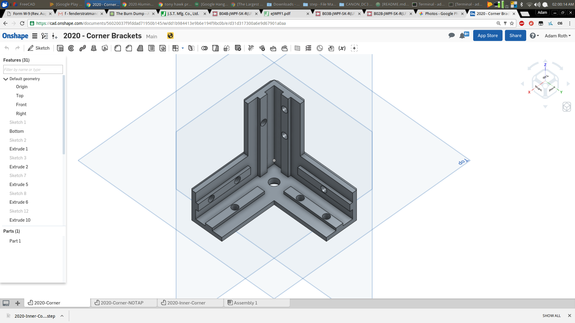
The next big change was a complete redesign of the frame mounting brackets. Over the course of the project I have been toying with quite a few ideas for frame corner parts, I wanted something that was strong but not too long to print. Initially the corners were made out of 3 printed pieces, printed flat on the print bed, this was chosen for its strength properties but suffered from complex assembly. The next iteration of this concept was to design it as one part this went through several iterations of modeling and test assembly before I came up with a combination of strength/optimal print time. After modeling a few different designs I settled on this :
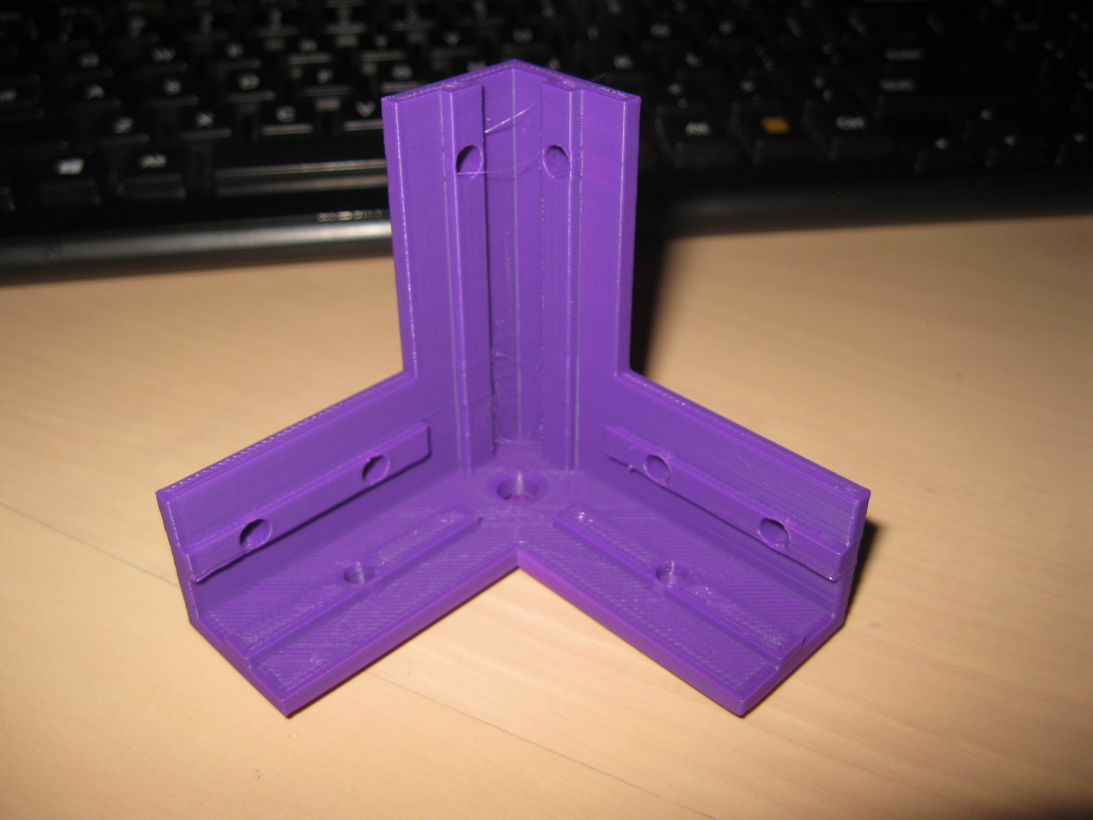 Test Print specs: PLA 40% infill 1.2mm perimeters, 0.2mm layer height.
I really like how this corner came out, its quite sturdy printed out of PLA, I didn't expect it to be so strong. The corner features, internal extrusions to guide the aluminum pieces, I'm playing with tolerances as I go, I might be able to print it for a snug locking fit with the aluminum. So initially these are meant to guide and aid in square assembly but I hope to get a dimension for a tight locking fit. The corner also contacts each aluminum piece at 3 points in a triangular pattern. The screw holes are meant for M4s except the end being meant for M6 for tapping the hole int he 2020 extrusion.
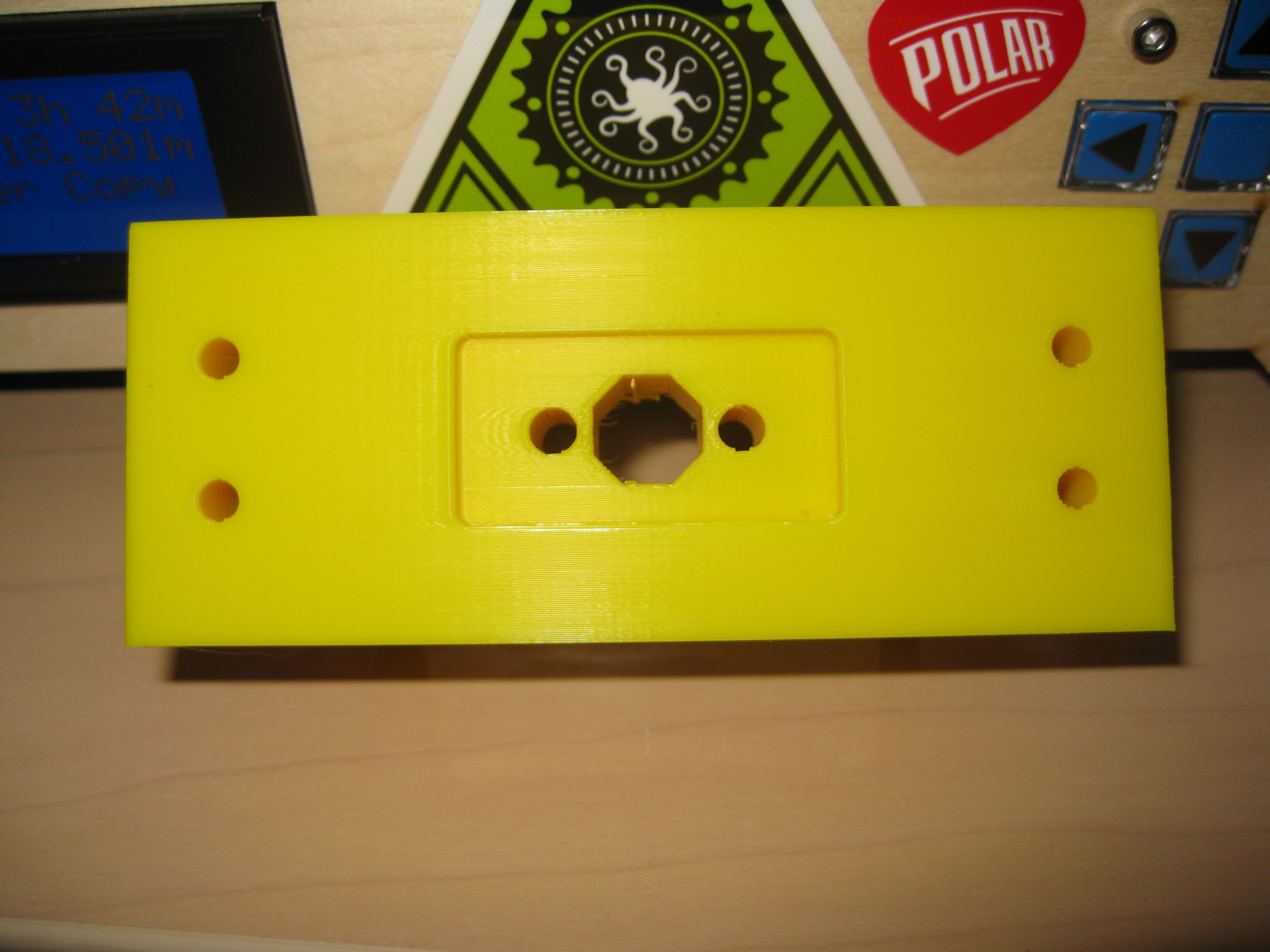
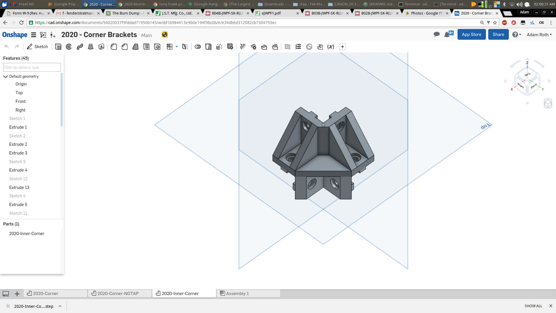
Next part was the inner corner, the initial inner corner pieces were difficult to print, had very poorly defined geometry, screw holes too close, and screw holes not dimensioned optimally for printing. The part is almost entirely the same but remodeled with correct screw hole dimension, correct screw spacing, and the ability to be printed flat without support material. After about 20 minutes of modeling in OnShape I came up with this:
Lastly I modified the spacer blocks for the motor blocks and idler blocks, all that was changed were the screw holes were spaced apart and resized for better printing tolerance. Thats all for now, stay tuned for further updates!
Discussions
Become a Hackaday.io Member
Create an account to leave a comment. Already have an account? Log In.