Close
0%
0%

Blinky 101

A step-by-step guide to blinky Hexabitz modules!

Similar projects worth following
As always, blinky LEDs are the best way to learn hardware! This project takes you into a step-by-step journey to assemble and program a demo Hexabitz array of five RGB LED modules (H01R00) and a single 3.3V DC-DC module (H03R00).

Learn how to assemble an array, load firmware to modules, use the CLI and write your own C code. Topics covered include synchronous and asynchronous messaging, input buttons, and remote memory access.

What is it?

An array of blinky LEDs to get you accustomed to Hexabitz hardware and software workflow. Feel free to send us any suggestions to improve or alternative methods you tried and worked out well

Components

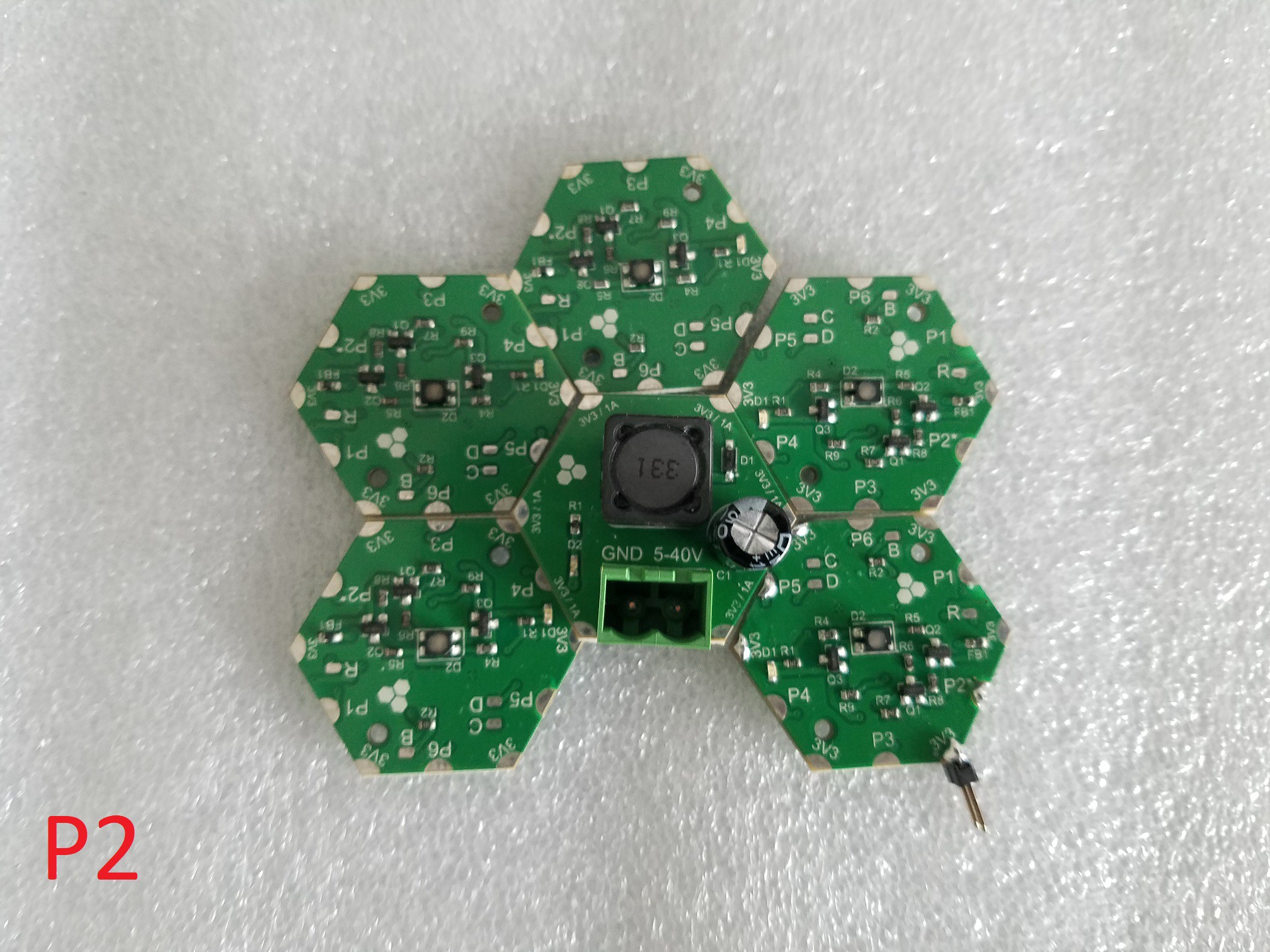
  • 5 x H01R00 Hexabitz RGB LED module
  • 1 x H03R00 Hexabitz 3.3V / 1A DC-DC buck power module
  • 5 x TL59FF160Q Momentary tactile push button

Estimated hardware build time: 10-15 minutes
Estimated software development time: 10-15 minutes for each example

Have suggestions about how to improve our demo projects? Feel free to comment below or send us a private message!

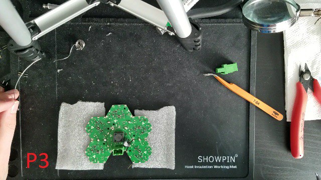
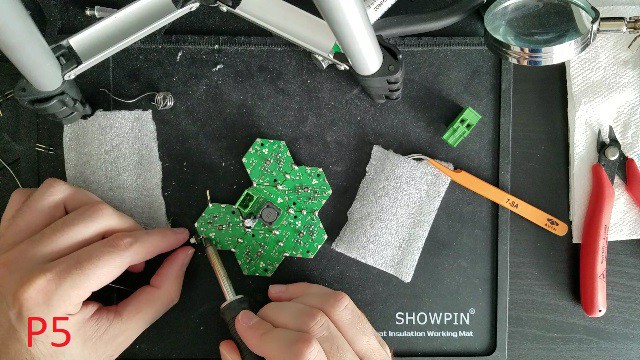
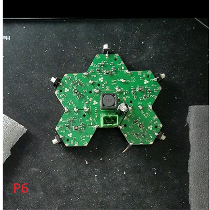
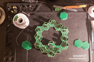
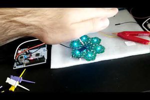
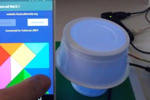
Hardware Assembly and Testing

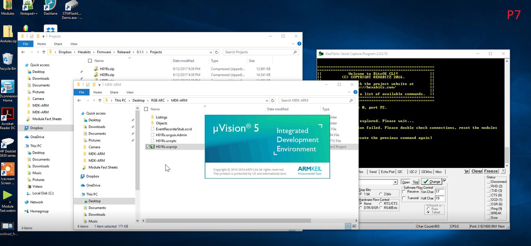
Please check project instructions for a detailed assembly and programming guide. Reference the pictures by their labels mentioned in text (P1, P2, etc). Happy making!

x-zip-compressed - 14.15 MB - 04/05/2019 at 11:35

Download

  • 5 × H01R00 Hexabitz RGB LED module
  • 1 × H03R00 Hexabitz 3.3V / 1A DC-DC buck power module
  • 5 × TL59FF160Q Momentary tactile push button

  • Example 1 Video - Step by Step Guide

    Hexabitz04/05/2019 at 11:12 0 comments

  • More Software Examples!

    Hexabitz04/05/2019 at 11:08 0 comments

    After you wrote you first program, here are more examples to get you busy!

    Example 2: 

    Make some dancing lights using broadcasted dim Message. Since the dim message enables separate internal timers on each module they end up out-of-sync in a beautiful way :D Note how message parameters with 32-bit size are cast into byte-wide parameters.

    You can copy the code below directly into a main.c file in User folder or rename the main_ex2.c file to main.c and replace the older one.

    /* FrontEndTask function */
    void FrontEndTask(void * argument)
    {
        // Random dancing lights
        
    #if _module == 1
        Delay_ms(500);
        BOS.response = BOS_RESPONSE_NONE;
    #endif        
    
      /* Infinite loop */
      for(;;)
      {
        #if _module == 1
            messageParams[0] = CYAN;            // color
            messageParams[1] = RGB_DIM_UP_DOWN_WAIT;    // mode
            messageParams[2] = (uint8_t)(10000>>24);    // period
            messageParams[3] = (uint8_t)(10000>>16);     
            messageParams[4] = (uint8_t)(10000>>8); 
            messageParams[5] = (uint8_t)(10000); 
            messageParams[6] = (uint8_t)(500>>24);        // wait
            messageParams[7] = (uint8_t)(500>>16);     
            messageParams[8] = (uint8_t)(500>>8); 
            messageParams[9] = (uint8_t)(500); 
            messageParams[10] = 0;                // repeat
            messageParams[111] = 0;     
            messageParams[12] = 0; 
            messageParams[13] = 1; 
            
            SendMessageToModule(BOS_BROADCAST, CODE_H01R0_DIM, 14);
            
            RGB_LED_dim(CYAN, RGB_DIM_UP_DOWN_WAIT, 10000, 500, 1);
            
            Delay_ms(500);
        #endif    
        
            
      }    
    
    }

    Example 3: 

    Aroadcast dim (exactly as ex 2) but fully-synchronized. Module 1 emulated the dim functionality and broadcasts color Messages with varying intensity. This way you keep the timer on a single module and keep them all synced. The 500ms delay before the loop is to ensure all modules finished booting before sending first Message.

    /* FrontEndTask function */
    void FrontEndTask(void * argument)
    {
        // Synchronized dancing lights
        
        uint8_t i;
        
    #if _module == 1
        Delay_ms(500);
        BOS.response = BOS_RESPONSE_NONE;
    #endif        
    
      /* Infinite loop */
      for(;;)
      {
        #if _module == 1
            // Up phase
            for (i=1 ; i<=100 ; i++)
            {
                messageParams[0] = 0;                        // Use color name
                messageParams[1] = MAGENTA;                    // color
                messageParams[2] = i;                        // intensity
                SendMessageToModule(BOS_BROADCAST, CODE_H01R0_COLOR, 3);            
                RGB_LED_setColor(MAGENTA, i);        
                Delay_ms(50);
            }
            
            // Down phase
            for (i=100 ; i>=1 ; i--)
            {
                messageParams[0] = 0;                        // Use color name
                messageParams[1] = MAGENTA;                    // color
                messageParams[2] = i;                        // intensity
                SendMessageToModule(BOS_BROADCAST, CODE_H01R0_COLOR, 3);            
                RGB_LED_setColor(MAGENTA, i);        
                Delay_ms(50);
            }
            
            // Off
            SendMessageToModule(BOS_BROADCAST, CODE_H01R0_OFF, 0);
            RGB_LED_off();
            
            // Wait
            Delay_ms(1000);        
        #endif        
            
      }    
    
    }
    

    Example 4: 

    Defining a  button on Module 1 and enabling its Click event. This event is used to set a flag in the event callback. The flag is used to generate some dancing lights.

    /* FrontEndTask function */
    void FrontEndTask(void * argument)
    {
        // Dancing lights enabled by button on Module 1
        
        BOS.response = BOS_RESPONSE_NONE;
        
    #if _module == 1
        // Setup the button
        AddPortButton(MOMENTARY_NO, P1);
        SetButtonEvents(P1,1,0,0,0,0,0,0,0);
    #endif        
    
      /* Infinite loop */
      for(;;)
      {
            
    #if _module == 1
            // Perform the dance
            if (buttonPressed)
            {
                RGB_LED_pulseColor(RED, 200, 100, 1);    
                Delay_ms(100);    
                for (uint8_t i=2 ; i<=5 ; i++)
                {
                    messageParams[0] = 0;                // Use color name
                    messageParams[1] = RED;                // color
                    // period
                    messageParams[2] = (uint8_t)(200>>24);
                    messageParams[3] = (uint8_t)(200>>16);
                    messageParams[4] = (uint8_t)(200>>8);
                    messageParams[5] = (uint8_t)(200);
                    // duty
                    messageParams[6] = (uint8_t)(100>>24);
                    messageParams[7] = (uint8_t)(100>>16);
                    messageParams[8] = (uint8_t)(100>>8);
                    messageParams[9] = (uint8_t)(100);
                    // repeat
                    messageParams[10] = 0;
                    messageParams[11] = 0;
                    messageParams[12] = 0;
                    messageParams[13] = 1;
                    SendMessageToModule(i, CODE_H01R0_PULSE, 14);            
                    Delay_ms(100);    
                }    
                for (uint8_t i=4 ; i>=2 ; i--)
                {
                    messageParams[0] = 0;                // Use color name
    ...
    Read more »

  • Software Example 1 - Coding 101

    Hexabitz03/09/2018 at 20:35 0 comments

    This is a simple example to show you the C coding workflow. We will send a broadcast ping message to all five LED modules so that they blink their red indicator LED. The message will be repeated every 500ms.

    In FrontEnd task in main.c, write the following before the infinite loop: 

    #if _module == 1 
    
    BOS.response = BOS_RESPONSE_NONE; 
    
    #endif

    And this inside the loop: 

    #if _module == 1 
    
    SendMessageToModule(BOS_BROADCAST, CODE_ping, 0); 
    
    Delay_ms(500); 
    
    #endif

    Recompile Module 1 and load. Note that the ping message takes zero parameters. The destination module ID (first parameter for SendMessageToModule API) is replaced with BOS_BROADCAST constant to broadcast the message everywhere.

    For more information, about implementing these APIs check our BOS documentation.

View all 3 project logs

  • 1
    Plan your array

    Planning is always wise before soldering things together! Stage the project components (P1) and plan your array design by aligning modules side-by-side in the shown orientation (P2) or any orientation you prefer.

  • 2
    Assemble the hardware

    It's time to do the fun stuff and assemble the array! Start by making basic solder joints to hold modules together (P3). This helps a lot moving forward.

    Then complete the remaining joints. You don't have to do all of them but it's preferable to provide structural support. Don't forget to work on the bottom side (P4)

    Finally add the push buttons (P5) (make sure you leave factory bootloader programming port P2 free if you did not load firmware before). Add any extra connectors/headers you might need and now hardware assembly is finished! (P6)

    Check this assembly video as well:

  • 3
    Get the source code

    Copy an empty H01Rx project from H01R00 code repository, rename the folder and open the uVision project located in the MDK-ARM folder (P7). You can also use firmware from the attached zip folder as well.

View all 7 instructions

Enjoy this project?

Share

Discussions

Similar Projects

Does this project spark your interest?

Become a member to follow this project and never miss any updates