 Radu Motisan
Developing the KIT1 raised several problems in hardware and software, and those were solved with multiple PCB iterations.
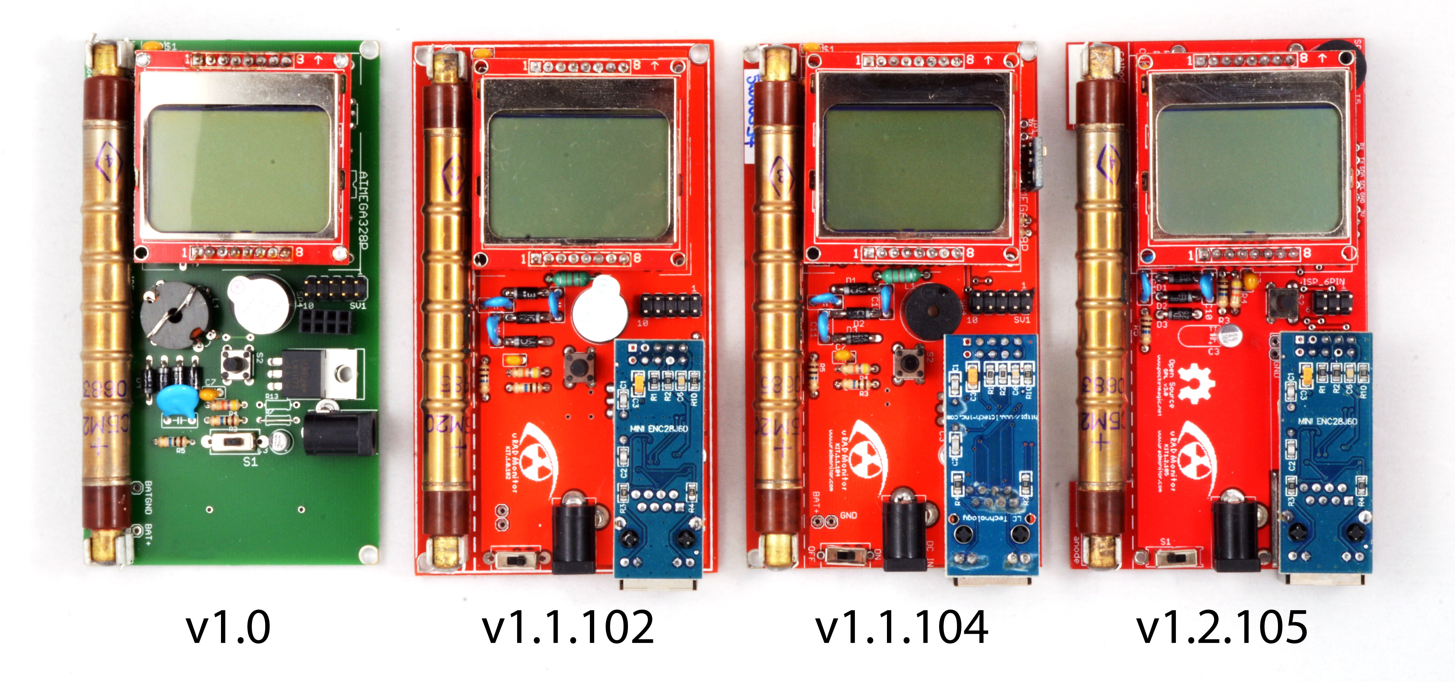
These are just of the few that were built. Initially, v1.0 used a ferrite transformer for the High Voltage inverter needed to boost the 3V Vcc up to 400V required by the Geiger tube. Making such a transformer was a difficult task, that would limit the production capabilities. The secondary needed about 400 turns of very thin wire:
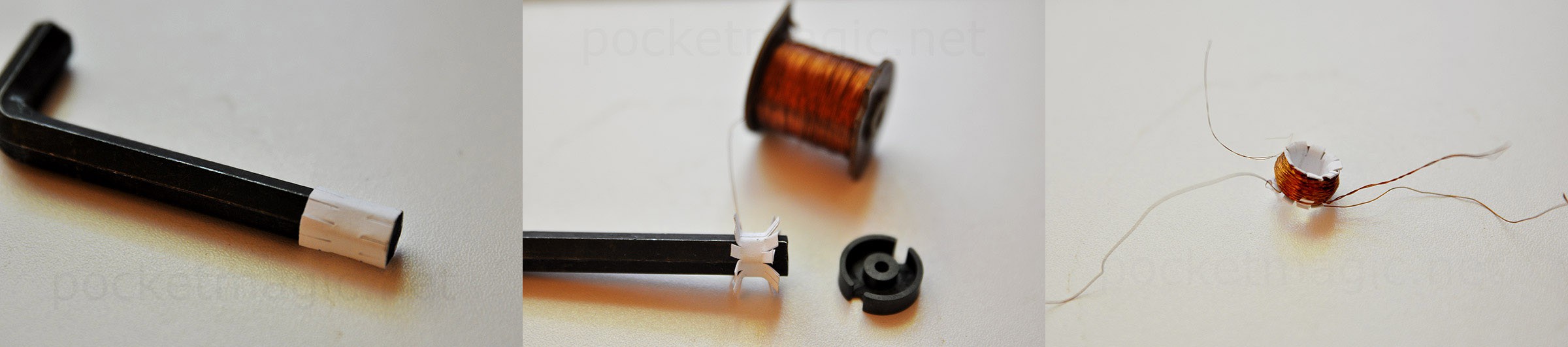
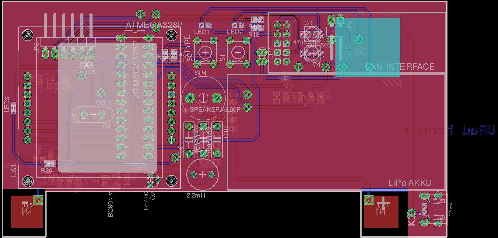
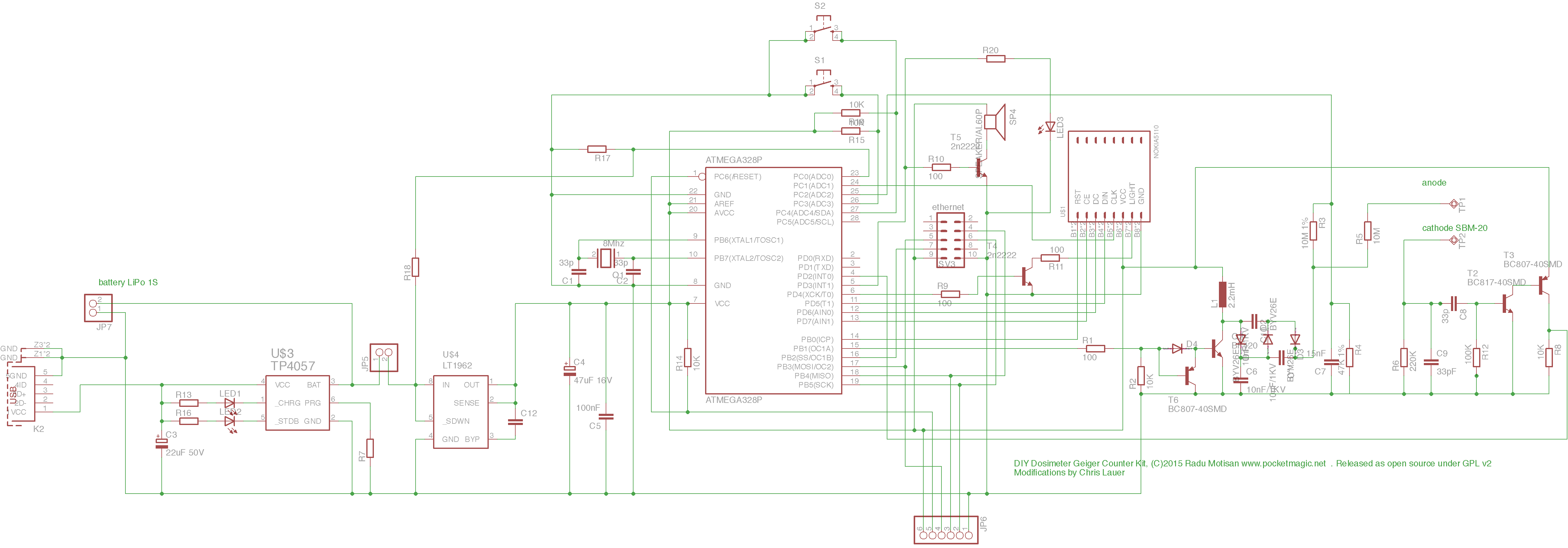
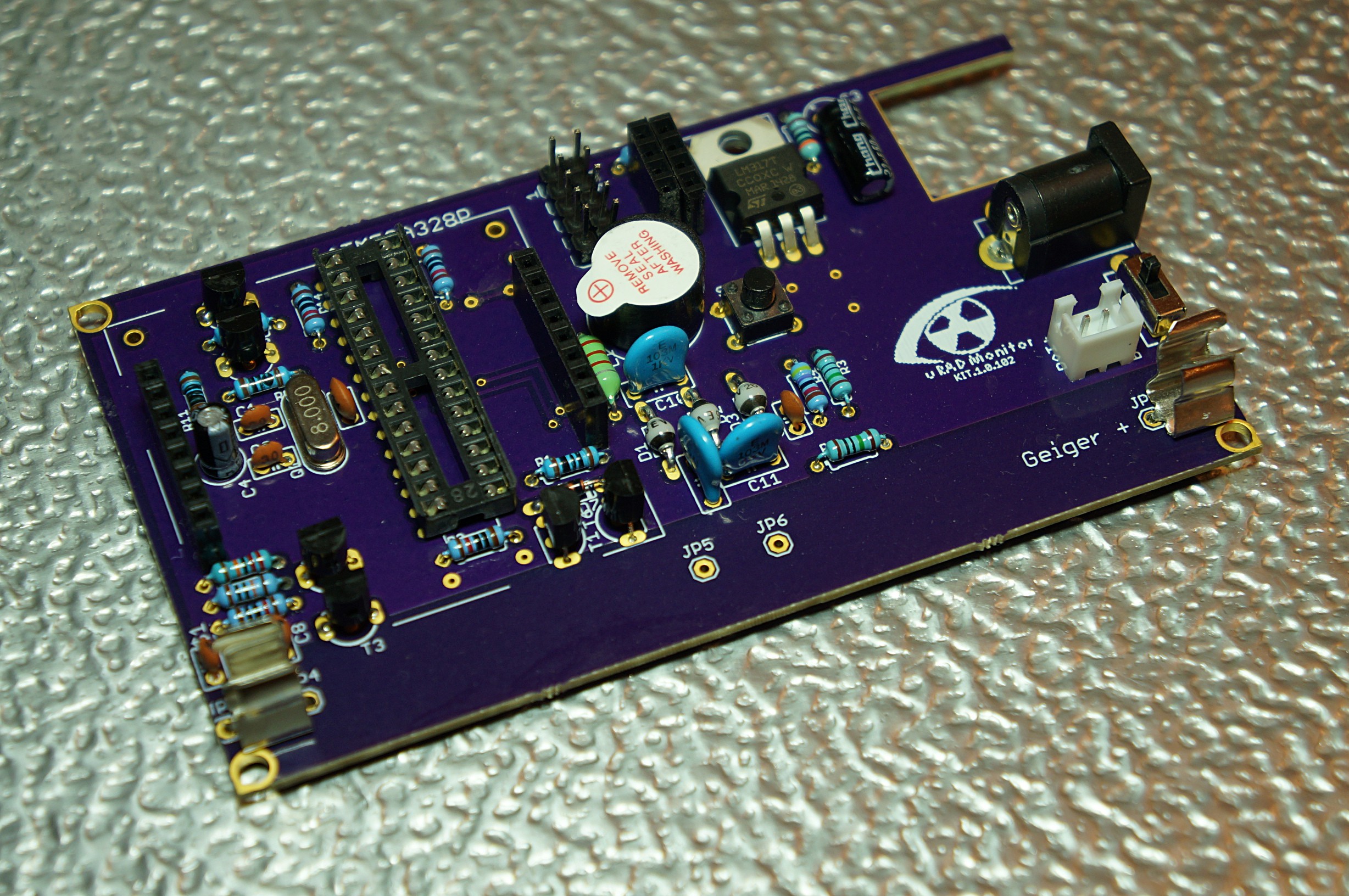
This was the most important change in the 1.1 versions, replacing the ferrite transformer with a simple inductor readily available in electronics shops. A voltage multiplier would compensate for the lower voltage of the new inverter, so we would still reach the 400V target needed by the Geiger tube. The switching transistor is blocked with a second PNP transistor to collapse the magnetic field on the coil faster, and generate higher voltage spikes. More on the development of a compact high voltage inverter here. This approach was used in the uRADMonitor model A as well, just with SMD components.
Version 1.1.103 is not visible in the first picture, but you can see it below. 103 was supplied after the successful indieGogo campaign in 2016, both as a solderable KITs and a readily assembled units.
1.1.104 brings an extension port, used to connect additional sensors. The Repository on GITHUB offers default code with a driver for the Bosch BME280 sensor included by default.
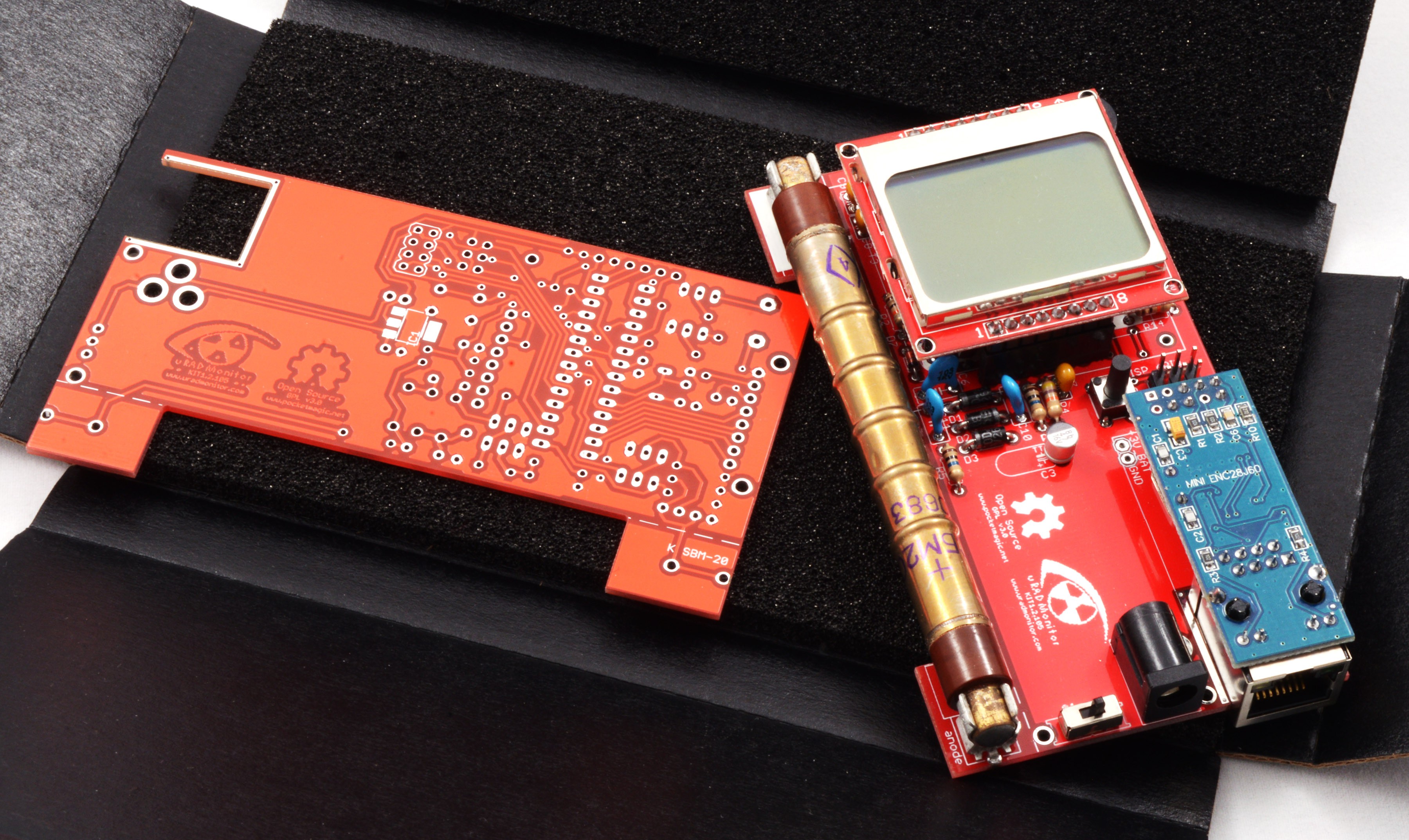
1.2.105 is a new kind of beast. The board has been reworked, the speaker and central button were moved, the PCB under the tube has a milling layer to avoid any interferences on the radiation detection capabilities, and the ISP connector went from the redundant 10pin variant to the 6pin standard.
The extension port outputs voltage, I2C and UART connections to the microcontroller. You can use it for virtually any kind of sensor using these protocols, like PM2.5 sensors, UV sensors and so on.
The GitHUB code comes with a dynamic ID allocation system, that means the units can join the uradmonitor network automatically.
Community variants
I already presented the advantages of the community support for this open source design in the previous logs. The KIT1 development took advantage of the creative effort of many makers out there.
Here are some pictures showing a few of them:
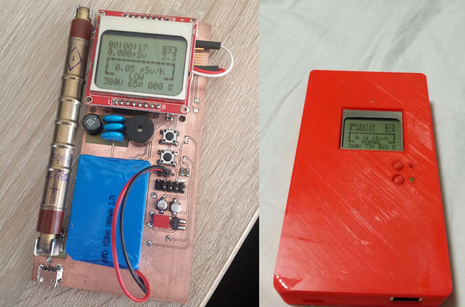
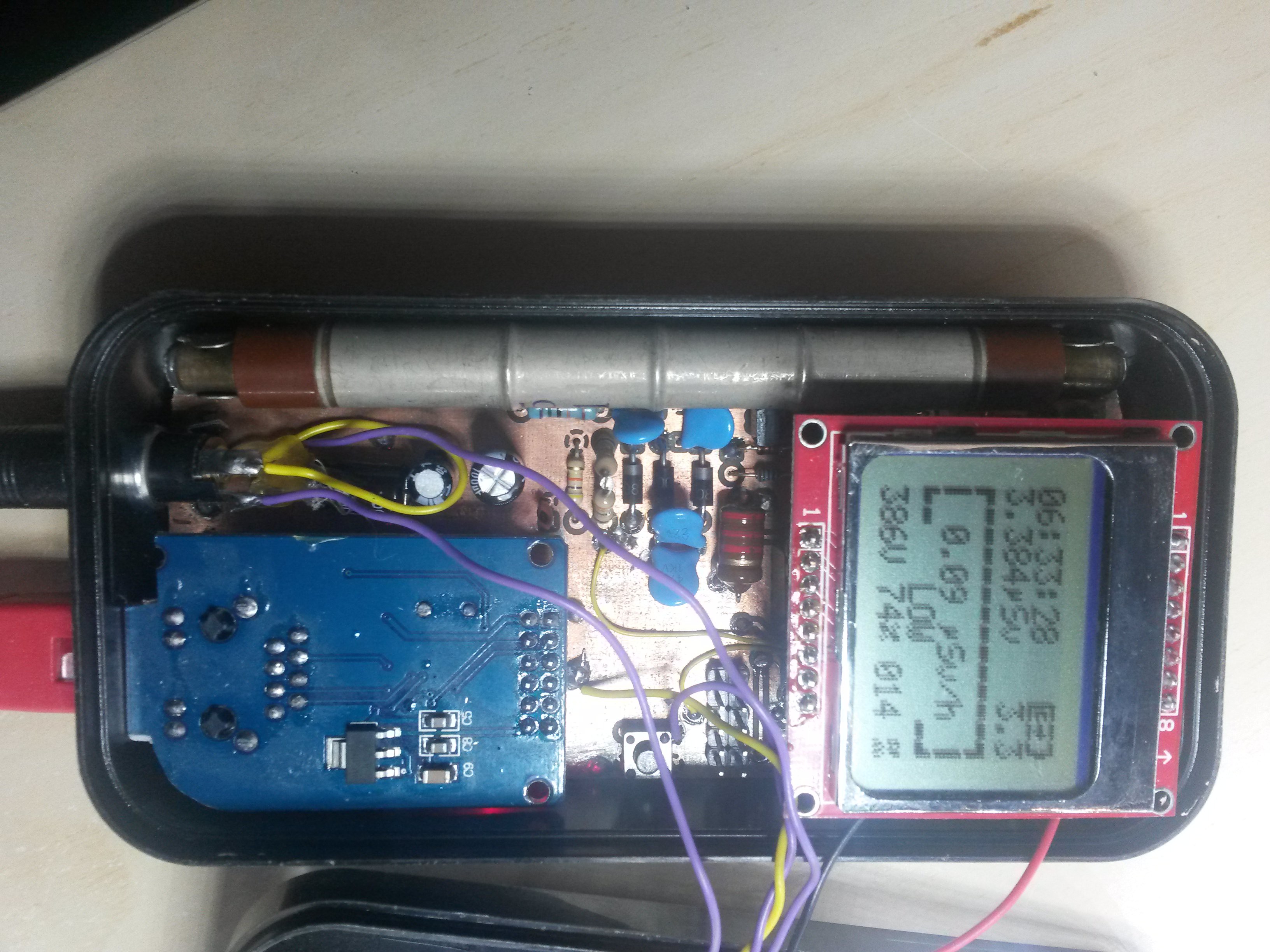
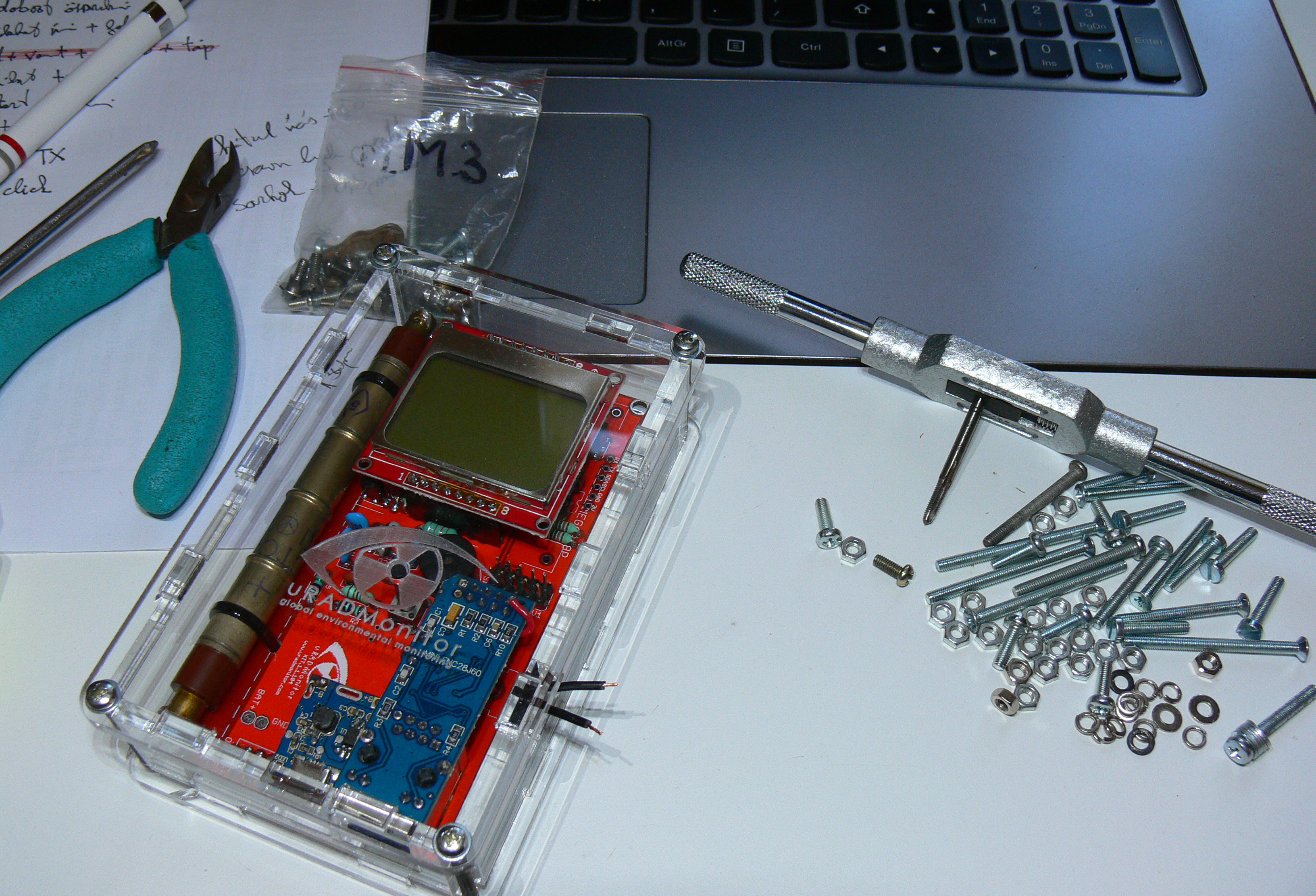
Chris and Frederik built a SMD variant, with a LIPO adapter to make the KIT1 fully portable. They also did a 3D printable enclosure:
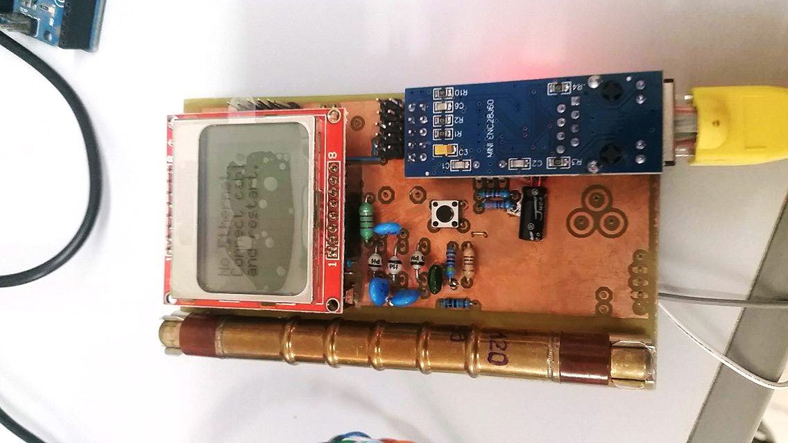
Otakar built his from scratch, using version 1.1.103 design files:

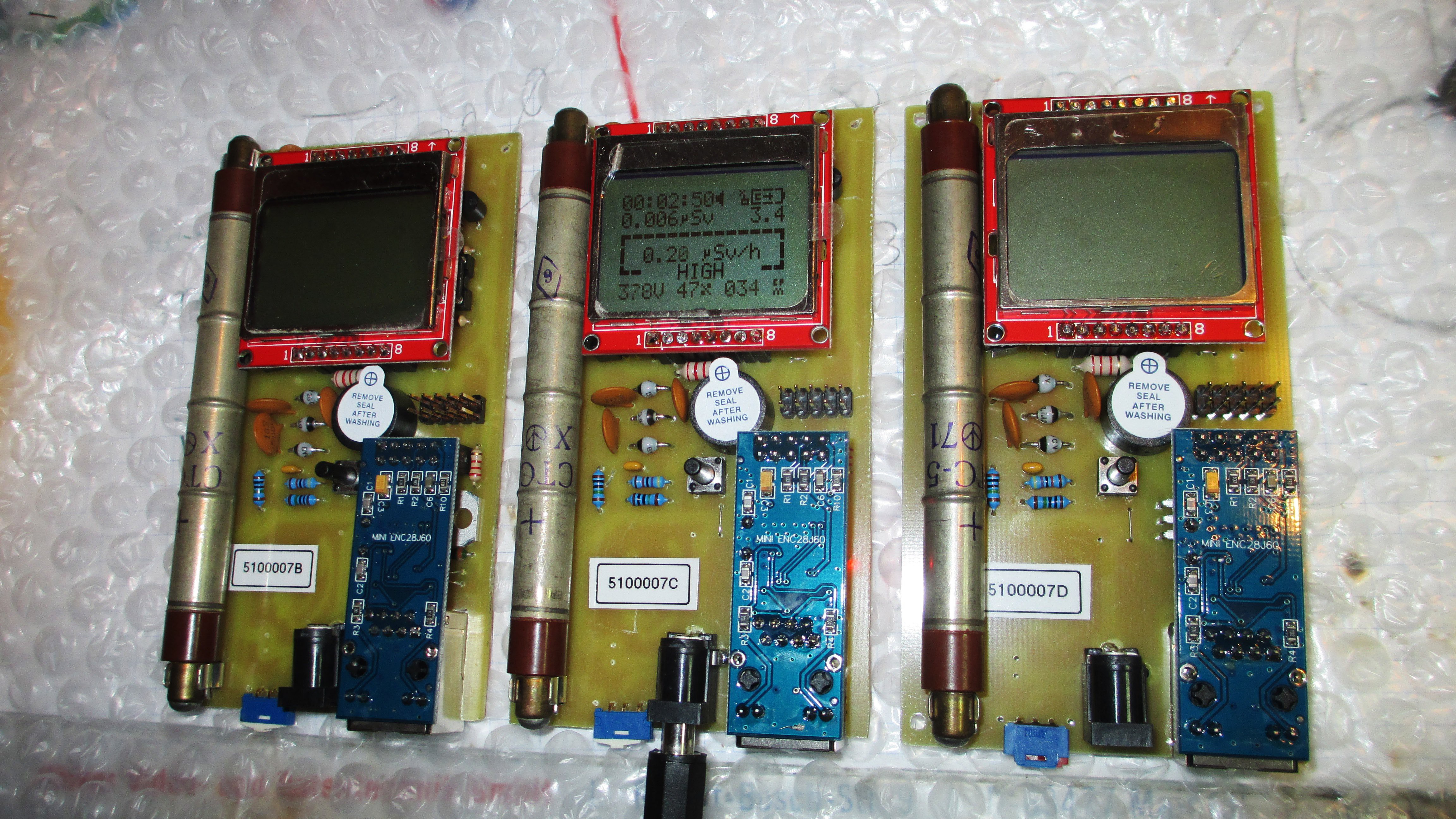
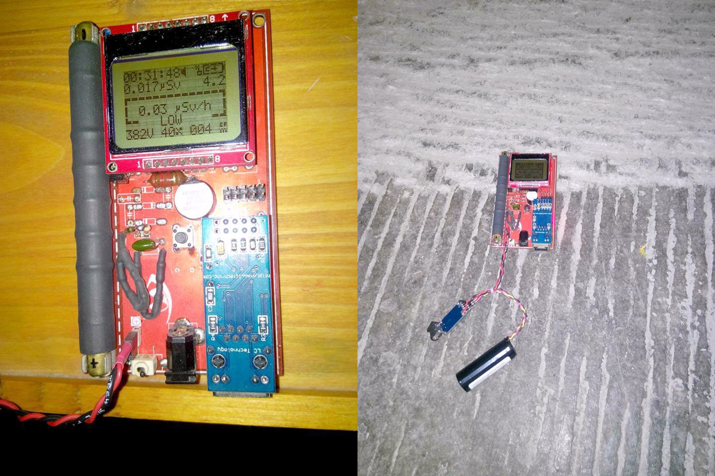
Tino, did an amazing job building 3 units from scratch:
Adrian used the excellent @oshpark services for his KIT1 unit which came out nicely:
Here's an interesting, highly customised KIT1 version:
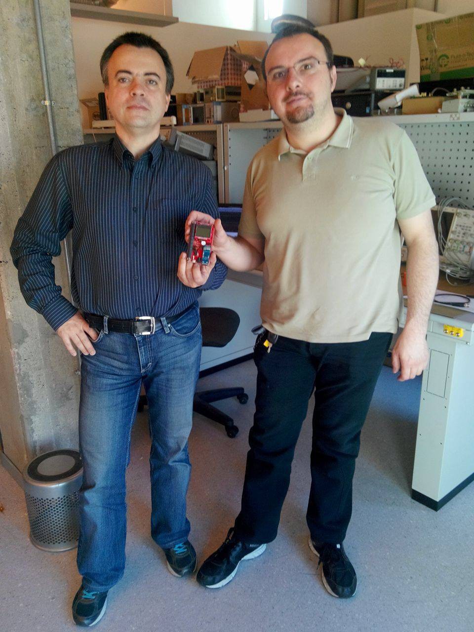
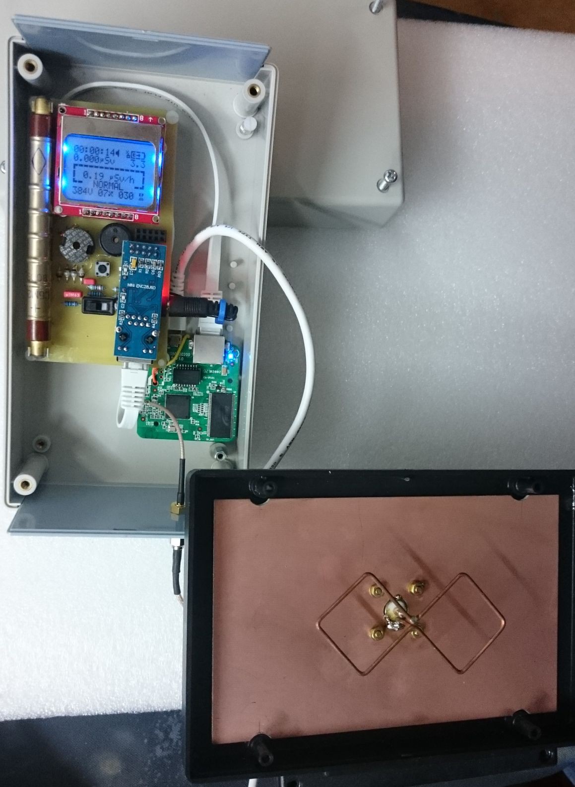
 Here's Horia and Fabio, good friends from the 4HV.org forum, with their fresh new KIT1, ready to take some of Fabio's X-RAY experiments:
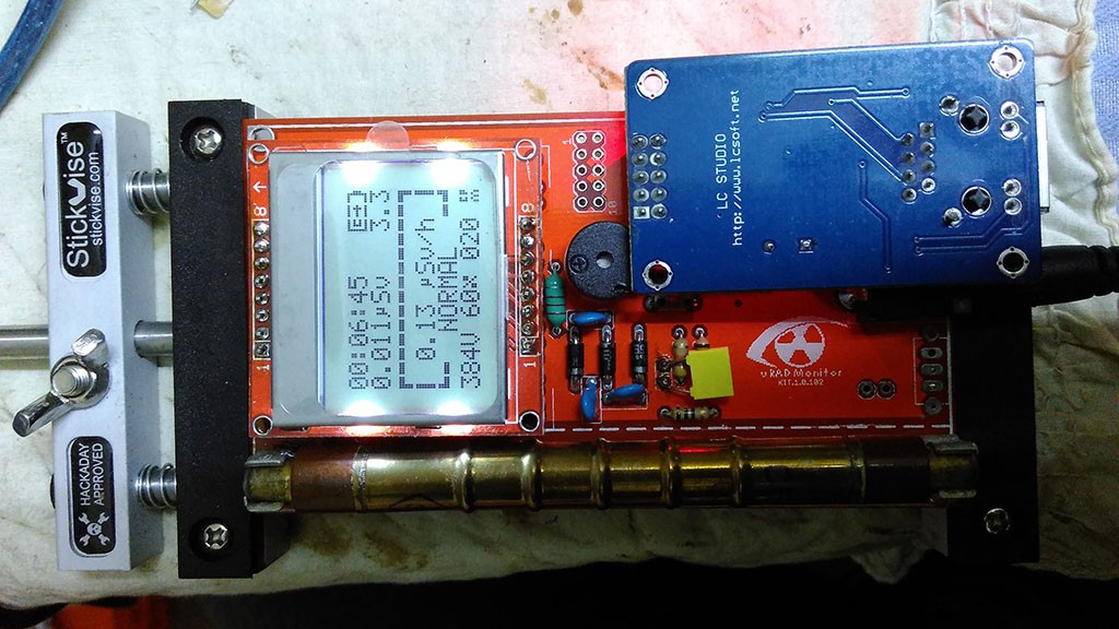
Malte built the new 1.2.105 on a beautiful orange PCB. Need to ask him where did he order it from. He also use a big fat inductor, that really can't go unnoticed:

Here's another one from Nicolas, including a custom enclosure:
Some simulations of the circuit and firmware some other guys were doing:

Sulley's unit running on 2 AA batteries (like originally planned):
 And the masterpiece created by Akos, that you saw in one of the previous project logs:
Here's another KIT1 built from scratch, most likely using toner transfer:
Hori's LiPO solution:
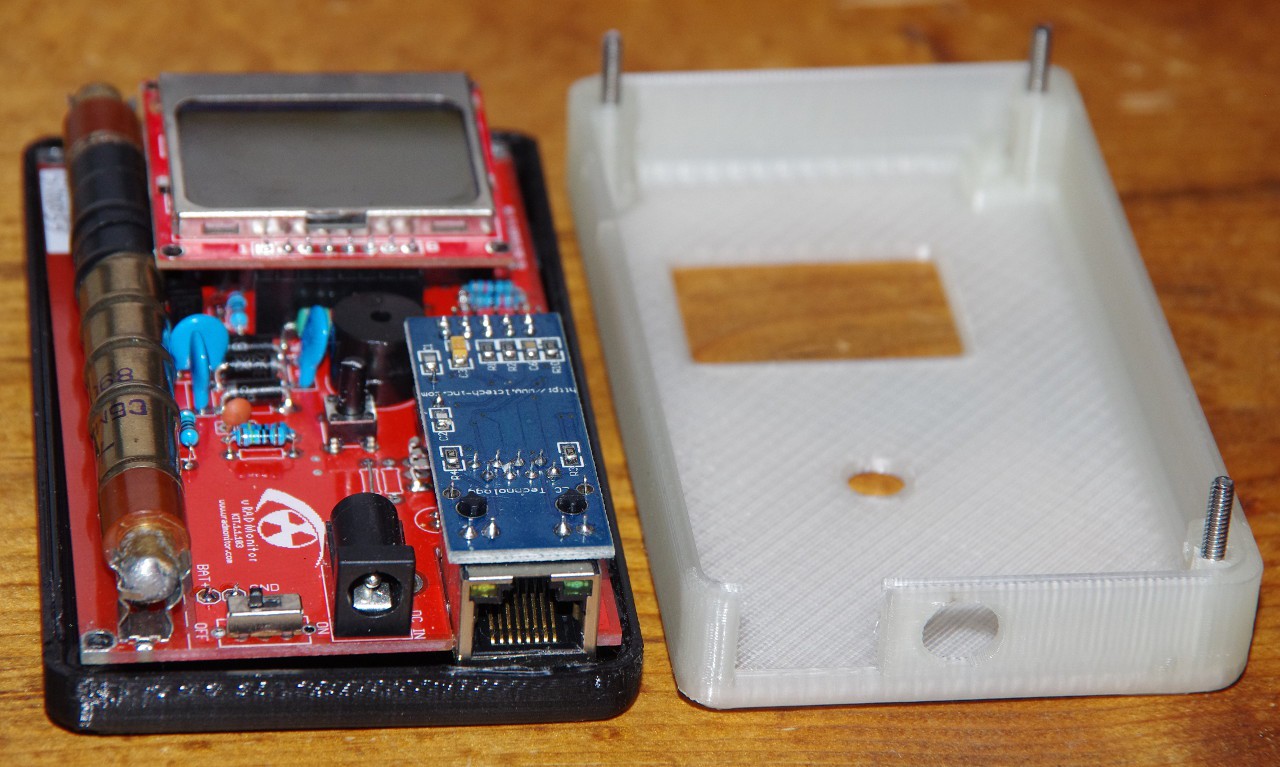
One beautiful 3D Printable enclosure, available on Thingiverse:
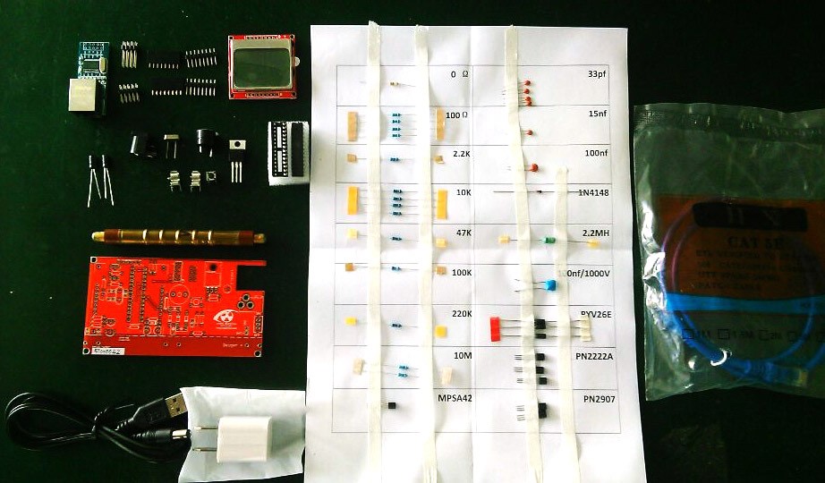
Tempted to build yours? I surely hope so! The latest design is available on Github. It will only take you a few hours to do a toner transfer PCB and have some fun soldering this versatile IOT device:
 You'll find the complete code there as well, or you can use this direct link. More information is available on the uRADMonitor blog, or you can see what other KIT1 builders posted on the forum.
Discussions
Become a Hackaday.io Member
Create an account to leave a comment. Already have an account? Log In.
I love version / iteration posts :)
Are you sure? yes | no
I'm glad you do! Most of my logs are just that . It's normal I guess, since things are getting improved gradually.
Are you sure? yes | no
Great post! Very interesting to see how the project evolved.
Are you sure? yes | no
thanks! your pcb-factory had its contribution too! :)
Are you sure? yes | no