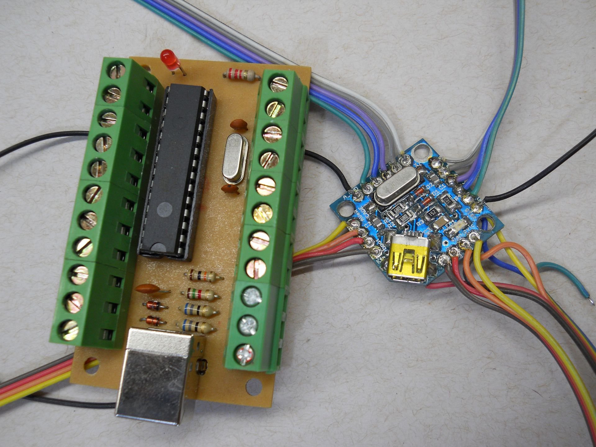
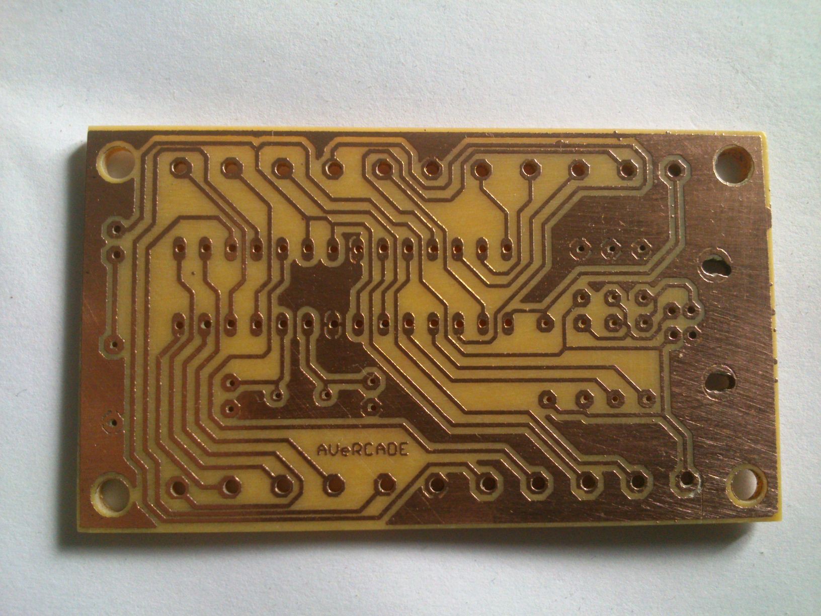
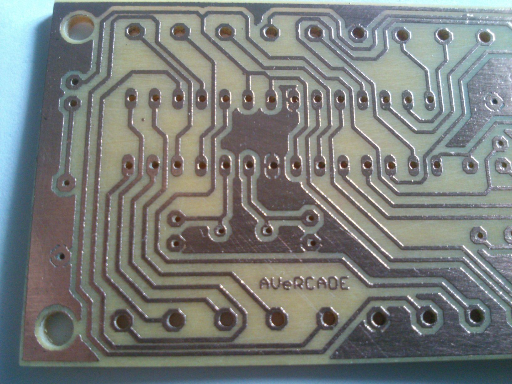
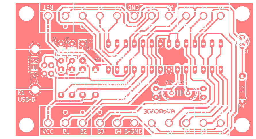
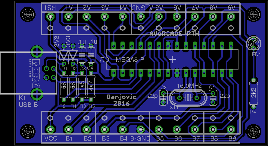
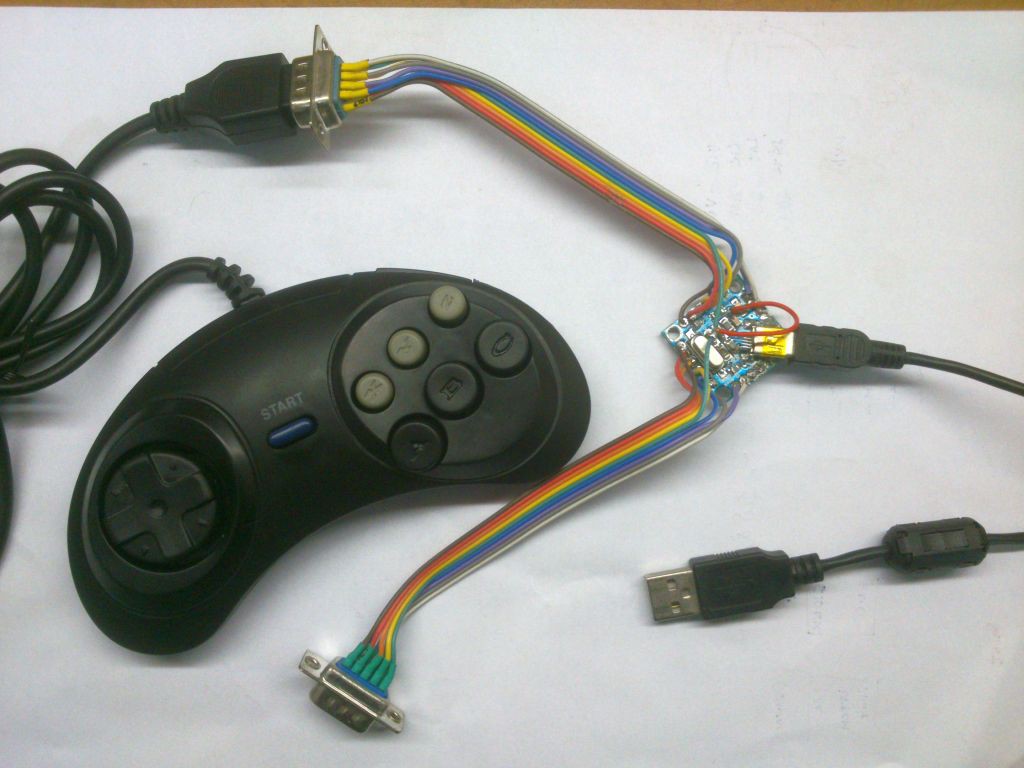
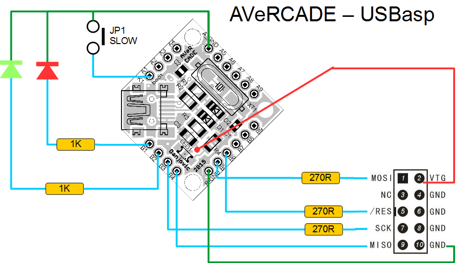
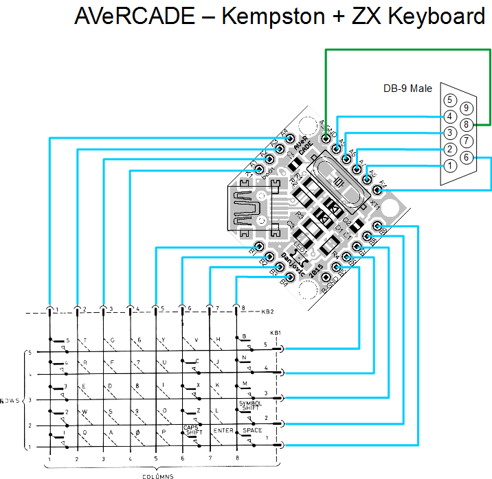
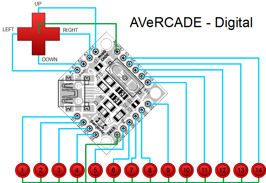
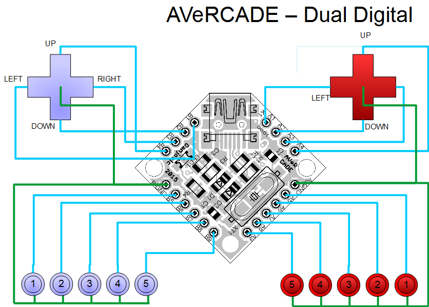
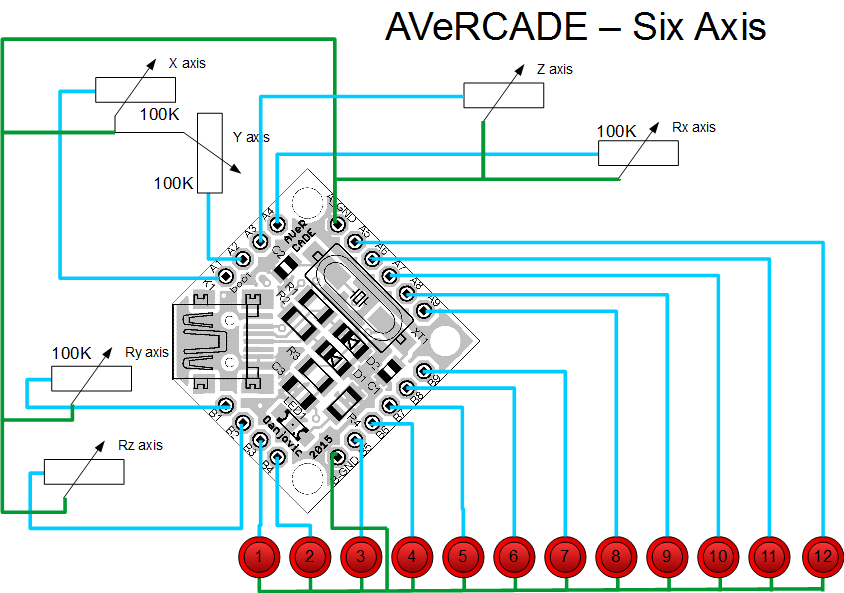
Close
0%
0%

AVeRCADE

Customisable USB adapter for arcade controls.

Similar projects worth following
AVeRCADE is a flexible USB adapter for arcade controls based on AVR and V-USB. It can also work as a generic development board, since it uses USBaspLoader to update the firmware.
  • 1 × ATMega328p AVR microcontroller, TQFP32 package
  • 2 × BZV55-C3V3 Zener Diode, SOD80 package
  • 1 × LED Red LED, 1206 package
  • 2 × 22pf Ceramic capacitor, 0805 package
  • 1 × 100nf Polyester/Ceramic capacitor, 1206 package

View all 11 components

  • Debouncing

    danjovic03/25/2017 at 19:26 0 comments

    Added timed sample of buttons (16ms) as a countermeasure for contact bouncing.Used Timer 0 to overflow at each 16ms

    	TCCR0 |= (1 << CS00) | (1<<CS02); // timer 0 prescaler 1024, overflow at FOSC/1024/256

    Then wait for Timer 0 overflow before sampling the buttons

    // Sample controllers each 16ms for 16MHz crystal (22ms for 12MHz)
    if (TIFR & (1<<TOV0)) {
    	Get_digital_controller_data();
    	TIFR |= (1<<TOV0); // reset overflow flag		
    }

    This prevents bouncing at later part of the code which sends a packed each time it detects any change in the controllers.
    ...
    	else
    	{// or if data has changed 
    		if (memcmp(&gamepad_report_1, &gamepad_report_1_old, sizeof(gamepad_report_t)) != 0)
    		{
    			to_send = 1;
    		}
    	}
    ...

  • Compiling issues

    danjovic03/06/2017 at 15:09 0 comments

    no such file or directory

    The makefile from github expects a directrory named 'output' to generate then read some files (like .map ) and a folder 'bin' to generate the hex files.

    To fix this error message:

    • create a folder named 'output' at the same folder of each project.

    • create a folder named 'bin' at the upper level which contains all projects (and contains the bootloader and usbdrv)

    That should fix the annoying errors until I fix the repository to include the missing folders.

  • Pinout Diagram for Single Face Board

    danjovic09/12/2016 at 23:43 1 comment

    I've lost some time debugging a firmware until I realized that I was taking the B1,B2,B3,B4 pins on the board by PB1 PB2 PB3 PB4 on the single face board. Then to avoid future mistakes such that I've drew the pinout diagram for this board.

  • Built and tested Single Faced PCB

    danjovic08/03/2016 at 02:40 0 comments

    I've just built and tested the conventional components, single faced printed circuit board for AVeRCADE. As I've imagined there were some small short circuits due to the proximity of some tracks but easily detectable with a multimeter. When checking with the magnifier glass I've realized that the board should have stayed longer in the etching bath because most of the short circuits were caused by very thin copper connections that remained from the corrosion.

    Here are the 1-inch board side by side with the Single faced board. It has roughly the size of an Arduino.

    The same firmware can run on both boards. After all they share exactly the same circuit.

  • DIY Single Face PCB: Built!

    danjovic08/02/2016 at 13:13 0 comments

    I've just etched the single face PCB. The results were good but I am thinking about changing the width of some tracks to reduce the probability of a short circuit.


  • Enhanced PTH board for homemade built

    danjovic07/28/2016 at 14:18 0 comments

    The component pads have been enlarged to ease the home built versions of the board.


  • New PCB layout: single face, through hole components

    danjovic07/26/2016 at 05:20 0 comments

    Just added another PCB layout with conventional components (through-hole) and single sided for ease of diy board manufacturing. The board measures 1.8 x 2.6 inches (roughly 40 x 70 mm) and has connections for VCC and RESET pins. The remaining pins were kept at the same configuration as the original board which means 2 rows of pins, A1-A9 and B1-B9.

    The Eagle files are on github under "circuit" folder.

  • Repository cleanup and new firmware available

    danjovic07/13/2016 at 03:55 0 comments

    Here are some news on the AVeRCADE project:

    • The repository tree was cleansed. Most of the firmware variations now share the same V-USB driver that was updated to the latest version (20121206).
    • The makefile now generates the .hex files on a "bin" folder at the root of the "Firmware" directory with different names according with the firmware variation and the microprocessor( Digital_Mega8.hex, DualDigital_Mega88.hex, etc...)
    • New firmware for Dual 6 button Sega Genesis (Mode and Start buttons also available).

    Things yet to be done

    • Fix the references of USBASP and Bootloader firmware so they use the same V-USB folder as the remaining firmware alternatives.
    • Make the composite device work (keyboard and joystick) so the ZX Keyboard + Joystick can continue

  • New Firmware: USBasp

    danjovic02/06/2016 at 02:33 0 comments

    I have modified USBasp code to run on AVeRCADE. Basically I have did 3 things:

    • Changed the USB pin definition to port D and enhanced the initialization code using USB connect / disconnect functions
    • Changed the clock speed definitions to run at 16MHz
    • Changed the LedOn / LedOff commands to drive the LEDs by the anode instead of cathode

    The connections to ISP and LEDs can be seen below. The jumper is optional since AVRDude allows to use the -B option to perform programming at low speed.

    The prototype can be seen below.

  • New firmware on sight: ZX Spectrum Keyboard

    danjovic01/27/2016 at 23:11 0 comments

    I have a new firmware on sight for Avercade. It is a composite device for reading a ZX Spectrum (or ZX81 ) keyboard matrix and converting them to keystrokes.

    The ZX matrix takes only 13 lines, leaving 6 more lines for reading an Atari compatible joystick.

    I plan to reuse code from C64 Key project for the keyboard part.

View all 31 project logs

  • 1
    Step 1

    Connections for Digital Joystick - 14 buttons

  • 2
    Step 2

    Connections for Dual Digital Joystick - 5 buttons


  • 3
    Step 3

    Connections for Six Axis - 12 buttons. Each potentiometer is 100K


View all 7 instructions

Enjoy this project?

Share

Discussions

tiago_cruz_lp wrote 10/11/2017 at 18:57 point

Boa tarde excelente projeto gostaria de saber se funciona o botão de home no Ps3?

  Are you sure? yes | no

Ricardo wrote 03/02/2017 at 22:38 point

Amigo, poderia me ajudar a compilar a versão digital 14 botões? Eu já fiz projetos com atmega8 gravando o hex com o software pony prog, porém não sei gerar o arquivo hex. Já tentei de várias formas e não consegui, tentei pelo Linux com o comando make, sem sucesso. Você poderia me dizer qual material eu preciso pra realizar está compilação? Vou usar o atmega8 e o cristal de 16mhz para a versão de 14 botões. Obrigado fique com Deus. 

  Are you sure? yes | no

Patrick Fonseca wrote 12/03/2016 at 19:13 point

Ci SMD 74HC14 Hex Inverter Schmitt Trigger use in opticar sensor joystick :D

  Are you sure? yes | no

alpha_ninja wrote 12/07/2015 at 00:49 point
[verified: no design files missing]

  Are you sure? yes | no

danjovic wrote 12/07/2015 at 01:11 point

Nice!! 

  Are you sure? yes | no

alpha_ninja wrote 12/02/2015 at 00:46 point

This is your one-week reminder to upload design documents: https://hackaday.io/project/7813-the-square-inch-project/log/28566-design-deadline

  Are you sure? yes | no

Mike Maluk wrote 11/14/2015 at 16:50 point

Man, that quarter really puts the size into persepective! 

  Are you sure? yes | no

danjovic wrote 11/17/2015 at 10:47 point

Really tiny, isn't it? Right after routing the board I've printed it real size on paper and got scared. In my mind came the question "Would I be able to assemble such small board?". Lol!. 

  Are you sure? yes | no

[deleted]

[this comment has been deleted]

danjovic wrote 11/09/2015 at 00:34 point

Thanks for the tip.

  Are you sure? yes | no

danjovic wrote 11/08/2015 at 00:35 point

By the way, thanks also for following the AVeRCADE along with KeyPass. 

  Are you sure? yes | no

danjovic wrote 11/08/2015 at 00:33 point

Thanks Craig! Let me see if I understood it correctly. The Pro Micro receives inputs from buttons (directly) and from PI (I2C) and send the inputs from PI (I2C) to host (USB) and the direct inputs (buttons) to PI (I2C). It looks like it has two roles then. 

Well, since the 32u4 does USB in hardware it might be relatively easy to make the AVR play both roles.  I think it is also feasible with ATMega8  bitbanging USB communication but anyway  if things (I mean Code) get confused you can still use an I2C port expander (PCF8574?) dedicated to read the buttons and your AVR code will deal only with USB<->PI communication.

  Are you sure? yes | no

alpha_ninja wrote 11/08/2015 at 08:59 point

Hey @danjovic, you can also reply to comments by clicking the gray reply link under the comment :)

  Are you sure? yes | no

danjovic wrote 11/08/2015 at 10:30 point

Ok thanks! I missed that sometimes, better use my glasses while using the computer, lol!

  Are you sure? yes | no

Craig Hissett wrote 11/08/2015 at 21:03 point

I think you'e got it mate ha ha!

To be honest with a footprint as small as the AVeRCADE I could fit two of them in the space of the the Pro Micro - use one just for the passing of the button presses to the Pi, and the other to monitor the i2c and send commands to the target PC.

In my head that makes sense, I think! :-)

Either way, your board is absolutely fantastic buddy!

  Are you sure? yes | no

danjovic wrote 11/09/2015 at 00:51 point

Thanks again Craig!

  Are you sure? yes | no

Craig Hissett wrote 11/07/2015 at 23:03 point

This is tremendous!

I have been looking at options for my #Handheld Programmer to control a set of Gameboy-esque buttons (direction pad, A, B select, start) and pass commands to a Pi via i2c, and also appear as a HID device when attached to a another machine (allowing the Pi to essentially send keystrokes to a target machine via i2c) - I hope that makes sense ha ha!

I have a handful of projects which I had been planning to use an Atmega32u4-based Pro Micros for; the tiny footprint of your great project would be much better suited!

I need some of these :)

  Are you sure? yes | no

Similar Projects

Does this project spark your interest?

Become a member to follow this project and never miss any updates