 danjovic
The original paddle controller has potentiometers wit 1MOhm resistance. Initially it was considered to measure the voltage across the voltage divider formed by the internal pullup resistors and the potentiometer, but the experiments performed showed that such arrangement produces a non linear voltage x position relation. Therefore another method shall be used: Measure the time it takes for a capacitor to charge from Vol to Vih. In other words, the capacitor shall be discharged by the measuring pin and then the pin is changed to input and the code shall count the time it takes for the input to flip state up to a certain time that shall be kept below a couple of milliseconds.
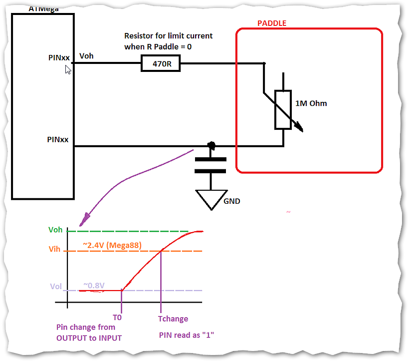
The supply for the potentiometers comes from a pin configured as output. Here's the updated circuit, notice the 1nF capacitors are a first approximation and shall be different for different microcontrollers (ATMega8 / ATMega 328).

Discussions
Become a Hackaday.io Member
Create an account to leave a comment. Already have an account? Log In.