 Ben Nortier
TL;DR - I built the first version of a leg:
 I have some goals for the the mechanical design of this open source robot - it doesn't help if you make an open source robot but it requires a $ 500 000 mold! These goals are:
- Use readily available manufacturing methods (3D printing, lasercutting, CNC routing)
- Use off the shelf components (servos, Arduino, Raspberry Pi)
- Use readily available materials (carbon fibre sheeting, 3d printed plastics)
I do want to make this into a kit, but anyone should be able to gather the components and make one themselves with the help of a makerspace.
I've been using Autodesk Fusion for the first time to design this robot, it's taken a bit of getting used to but I do like the parametric design capabilities (I'm used to using Rhino). Version one of the robot looks something like this:
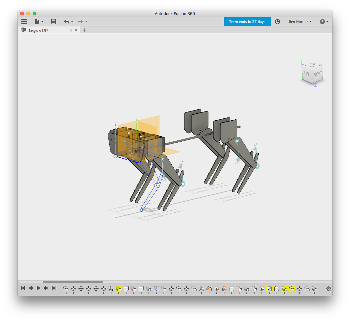
- It has 4 legs
- Each leg has 2 segments, with a servo and link each
- The shoulder can rotate
So we have 3 degrees of freedom for each leg, 12 in total. Servos are relatively cheap compared to torque motors ($15 vs $3000) so I'm going with servos for now.
Some people who have built similar projects actuate the legs with the servo directly. I'm not convinced by this. I'm also not convinced that using a linkage is the right approach. Each has its advantages and disadvantages. In essence though, I don't like putting the servo under strain perpendicular to the servo axis, so in this design the leg segments have their own joints based on a metal shaft (more on this later).
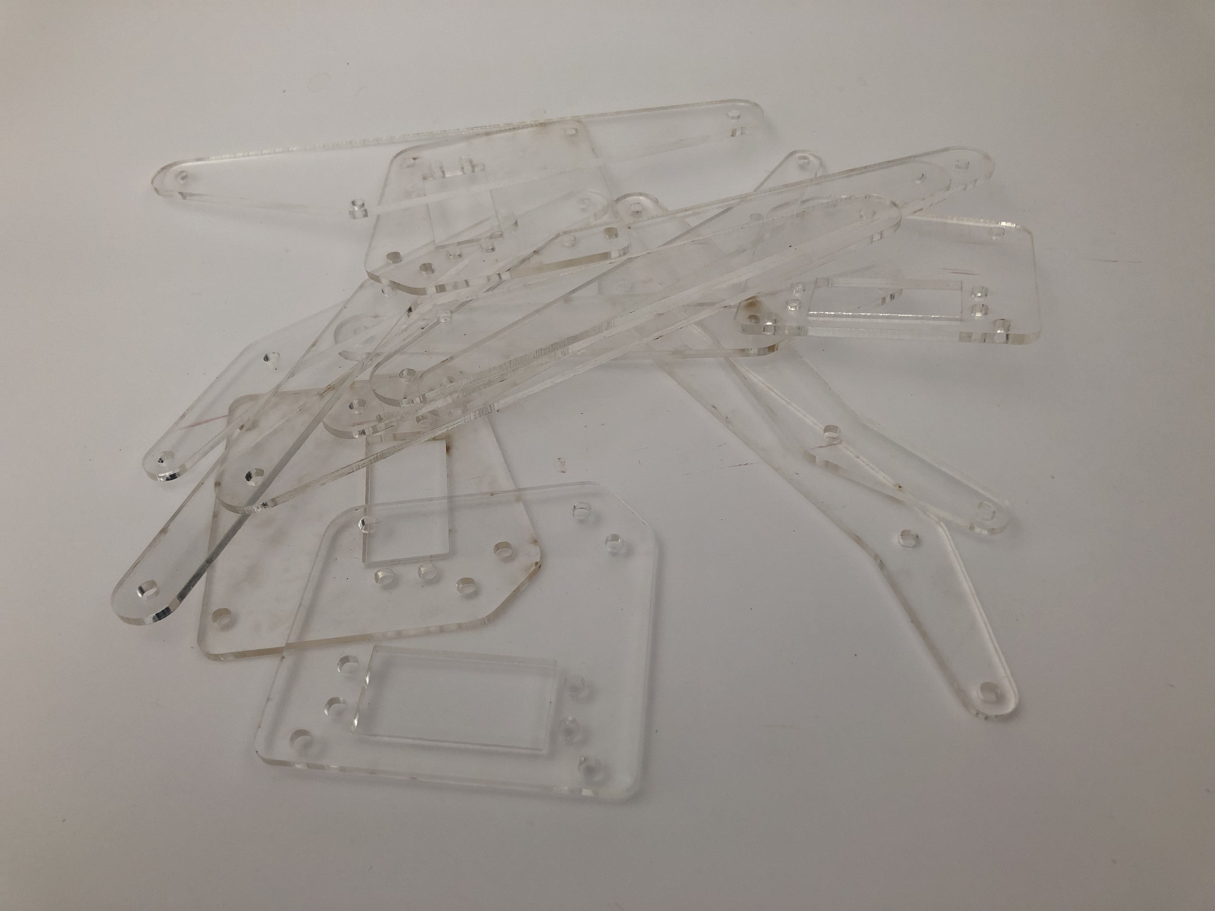
I had the prototype parts lasercut from acrylic (NB the thinking at the moment is to use CNC routed 3mm carbon fibre sheets, NOT 3mm acrylic sheets, but I have some acrylic handy and it's cheap so I'm using that for now)
First set of parts:
And the first problem:
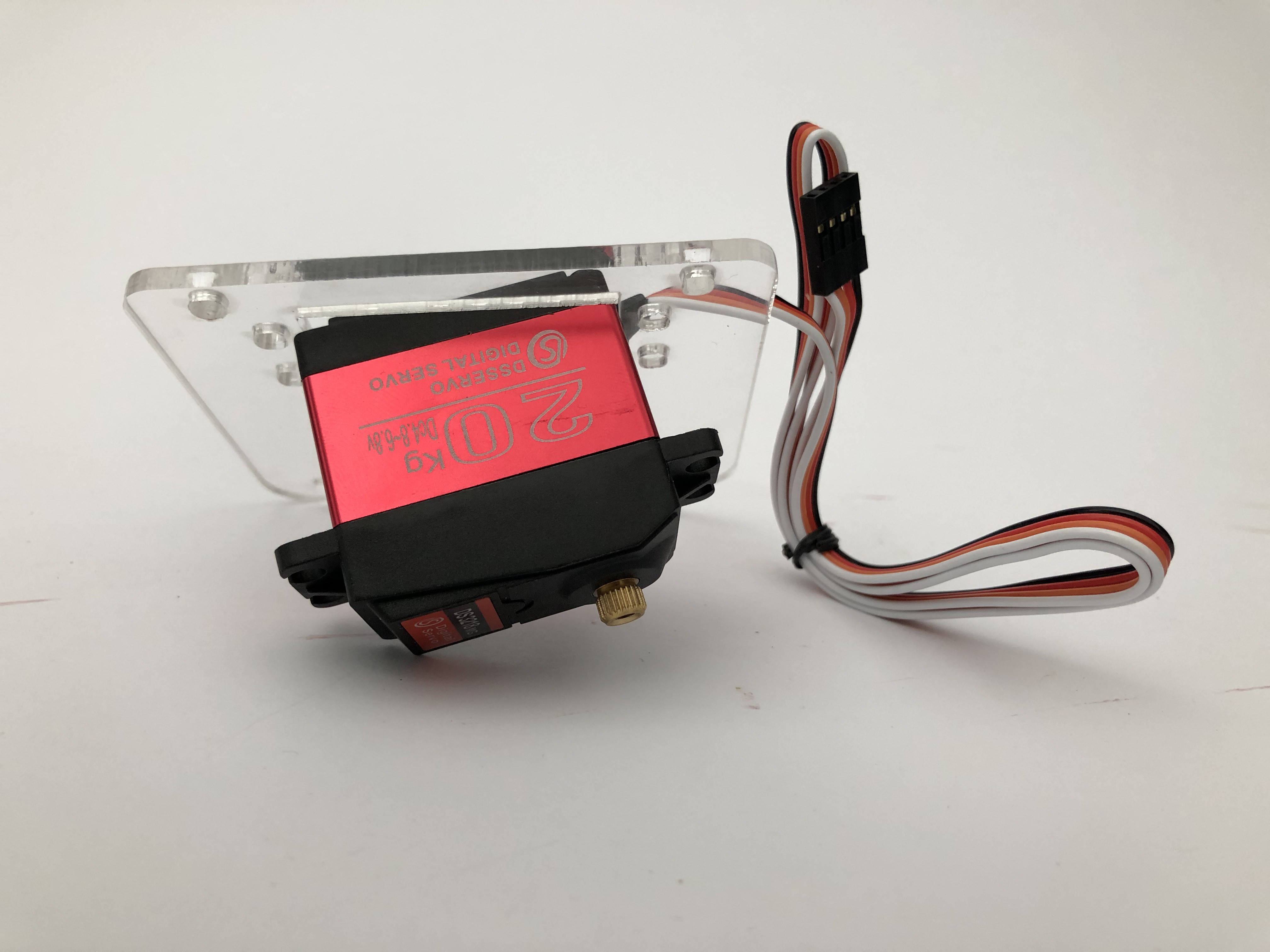
I didn't take into account the insertion angle of the servo :/
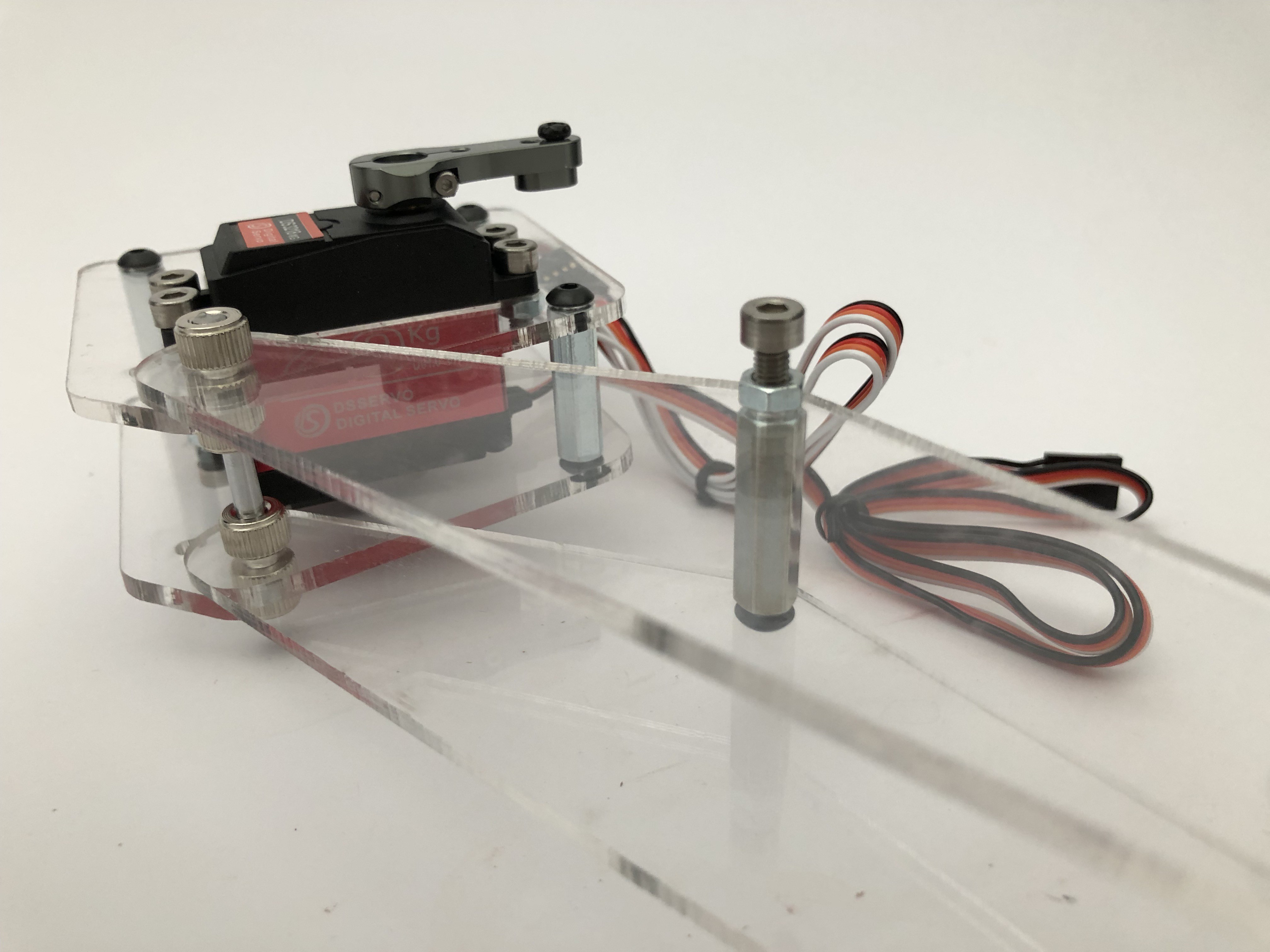
Took out the file and started filing... and here's the two servos embedded:
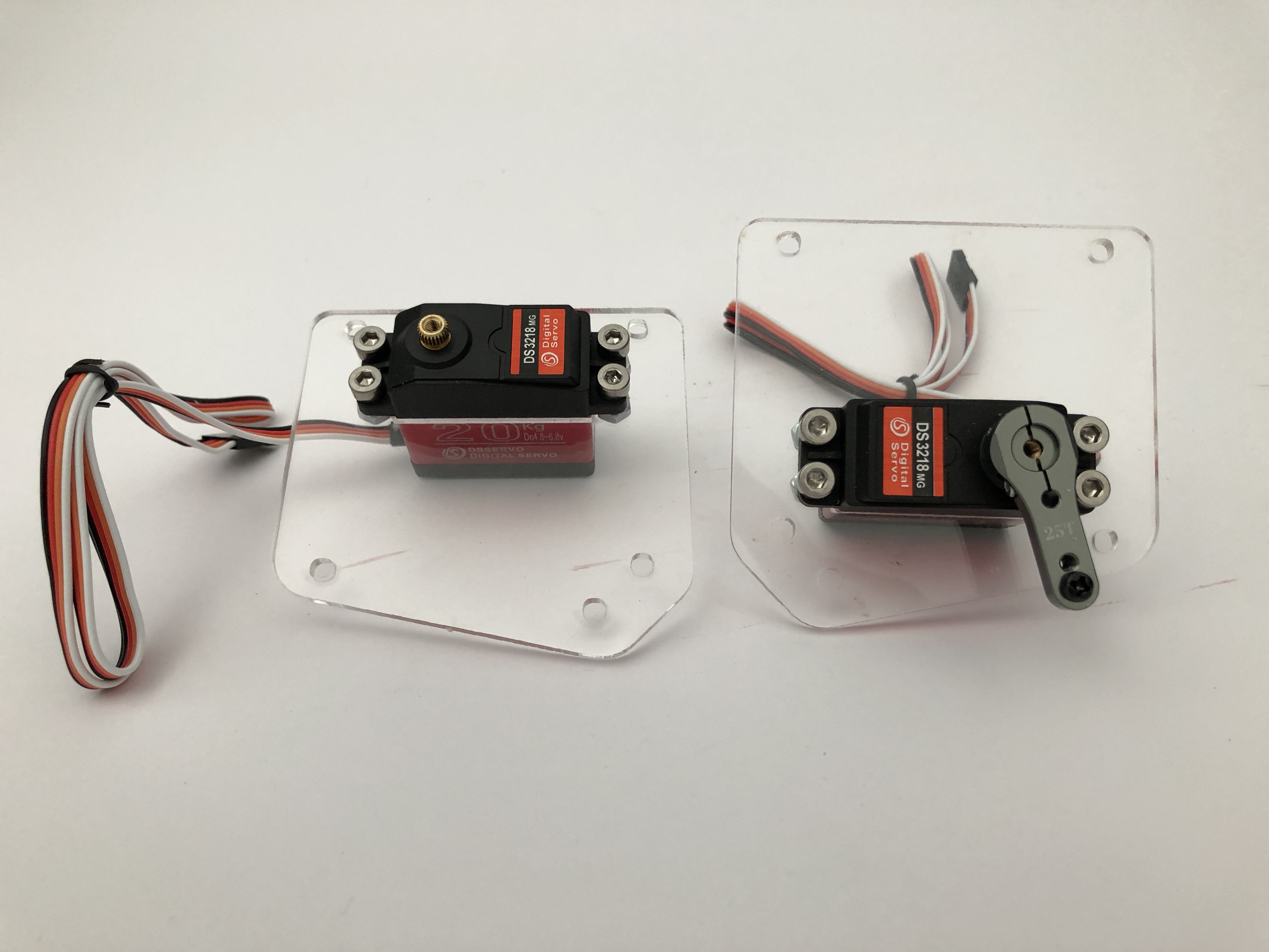
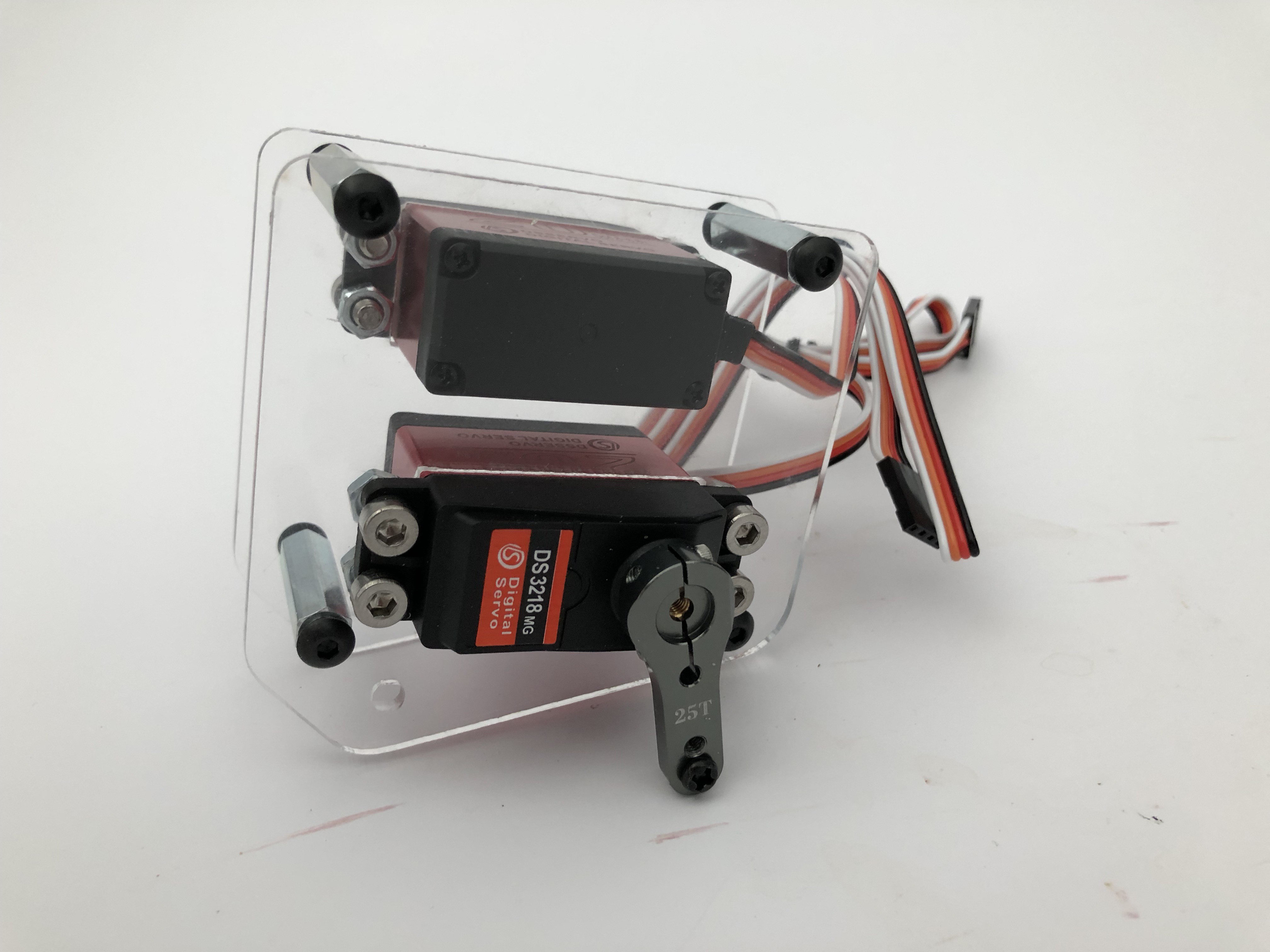
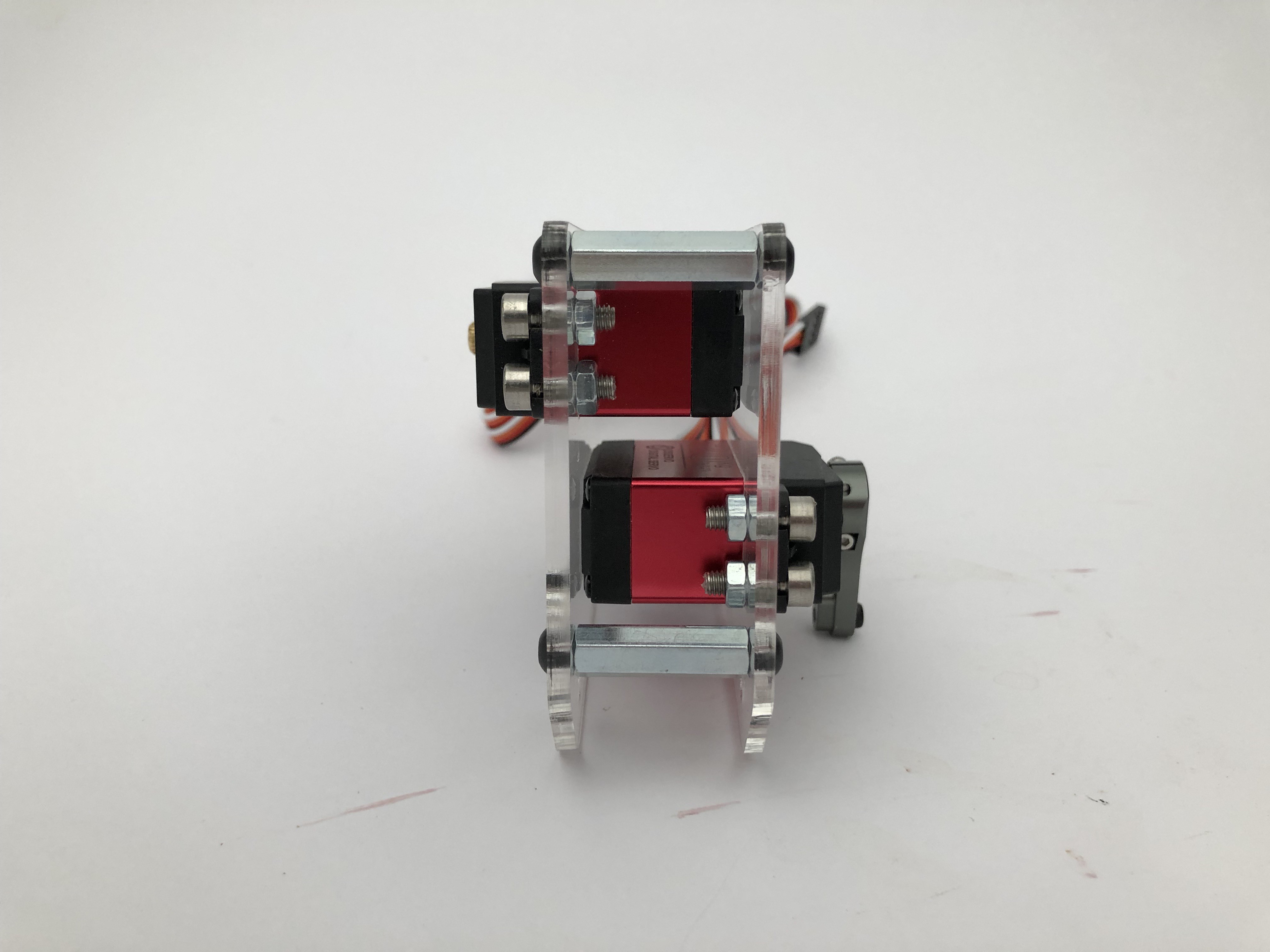
You can see I used 25mm standoffs. The nice thing here is the servos are 28mm from bottom to where they meet the acrylic, which is 3mm thick. So they fit snugly against the opposite layer:
Slick!
Then I hit my 2nd snag :/
In the one corner, a 4mm Precision Round Bar with a hardness of HRC60-62.
In the other corner, a small hacksaw.
Hacksaw lost badly. It didn't even make a scratch!
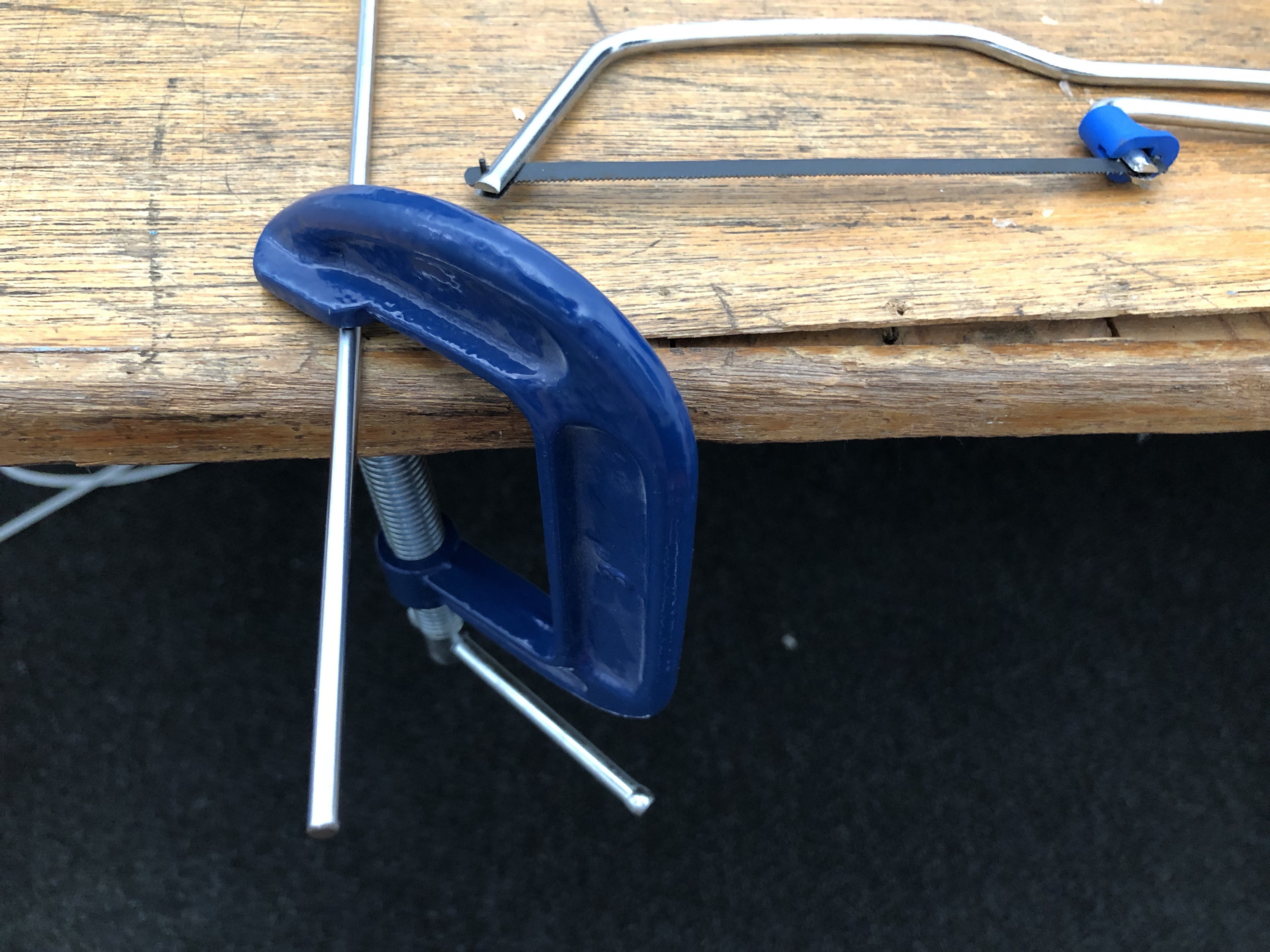
What to do.... I went to the hardware store to find a 4mm wooden dowel to use temporarily... but got a 5mm one instead. Fail.
Then I thought about something.... I have a little drill that also has tiny grinding discs. Which I've never used... Will it work?
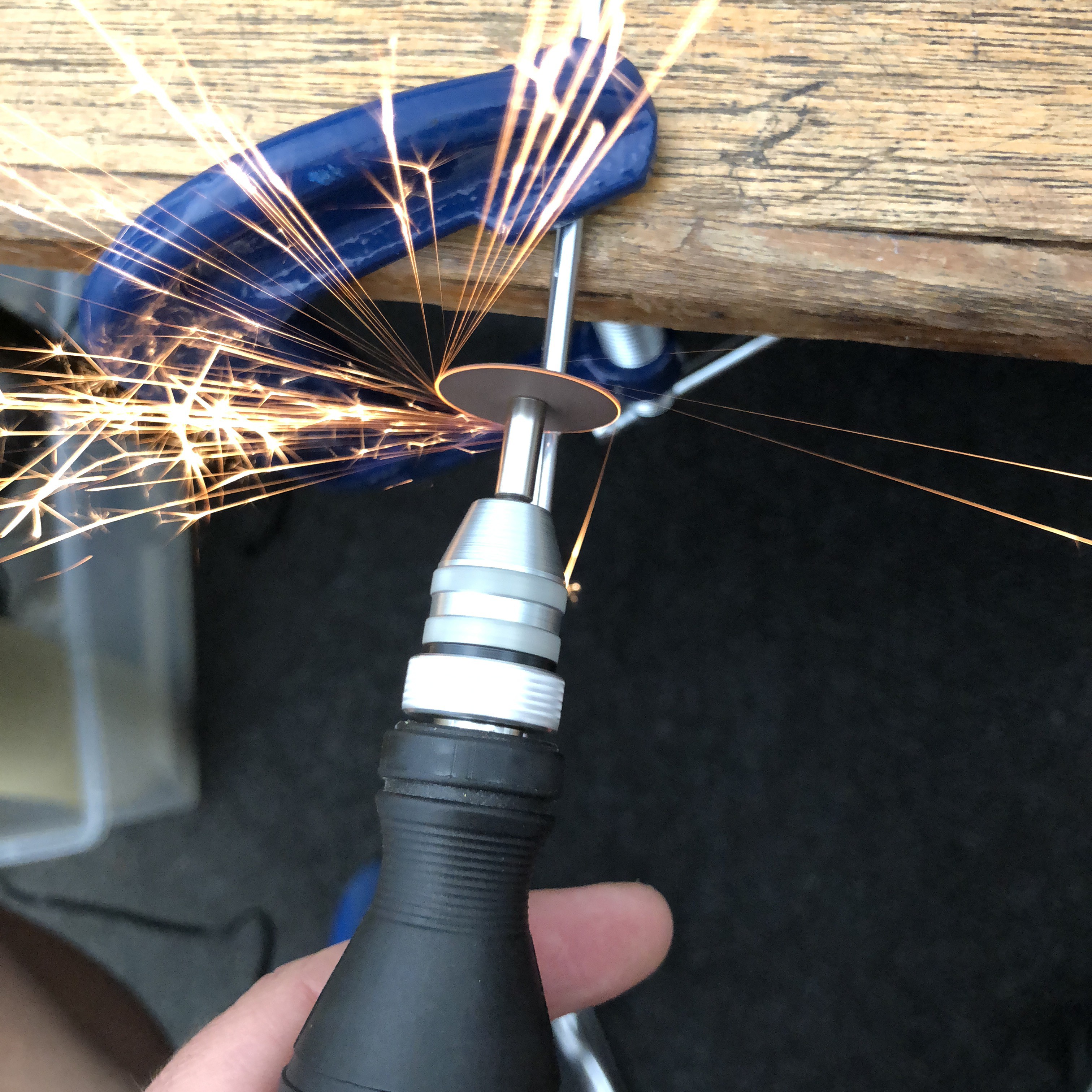
Sparks! Here's to buying unnecessary tools. Got some safety glasses and set to work.
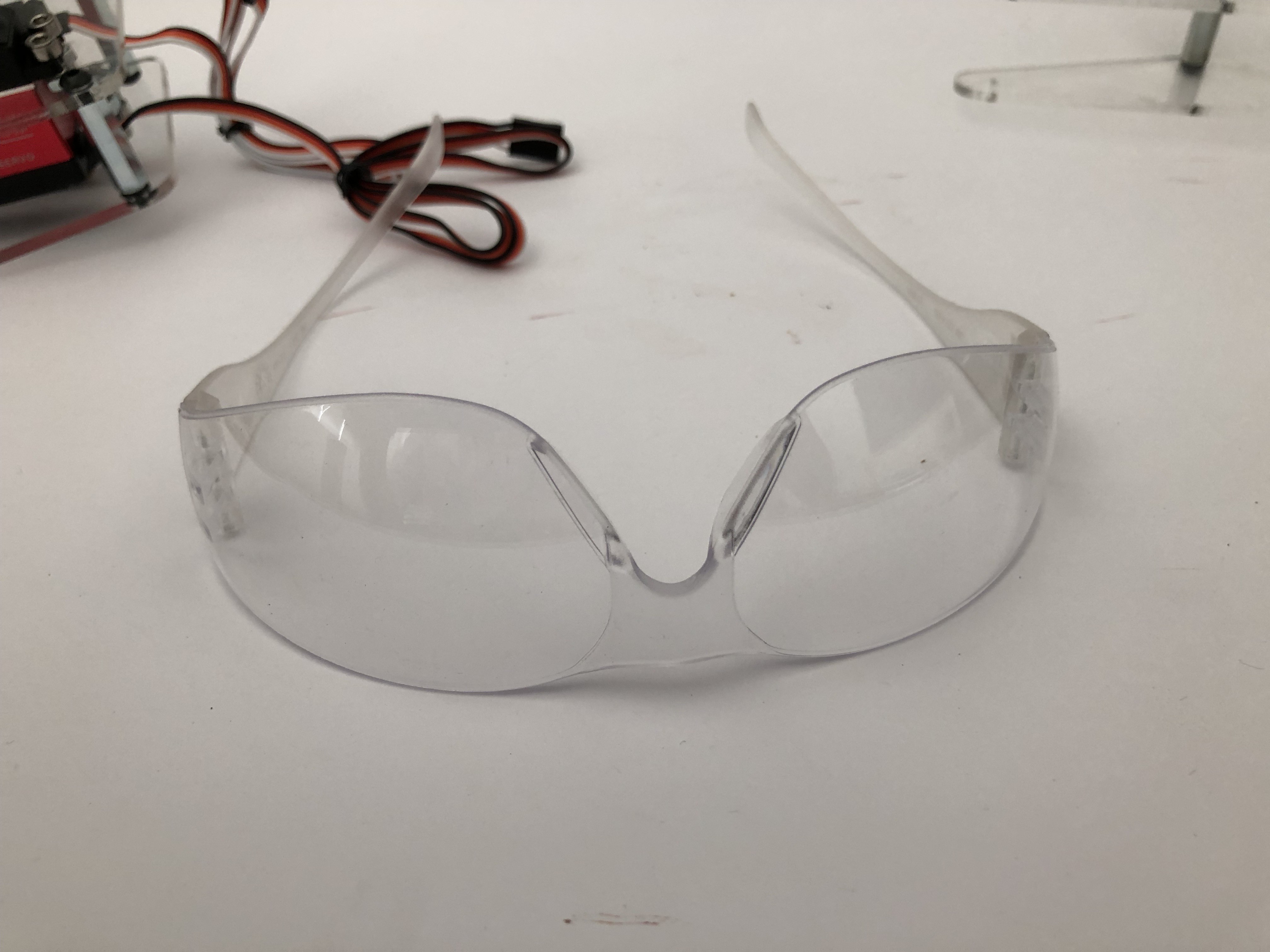
Shout-out to Zortrax who supplies a set of safety glasses with their M200 3D printer! That machine is fantastic. Highly recommended.
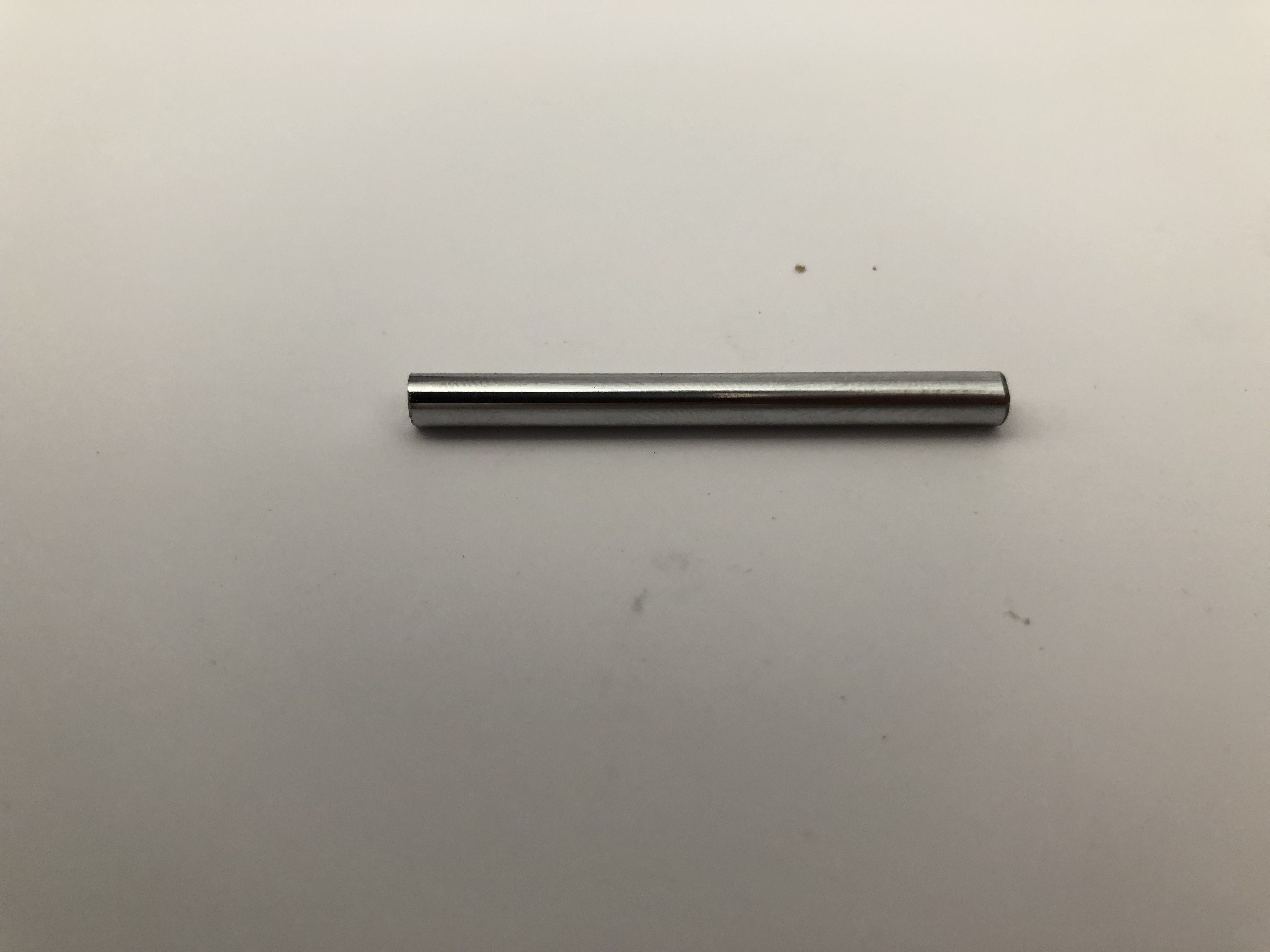
The world tiniest angle grinder did the trick. 1 times 4mmx44mm shaft:
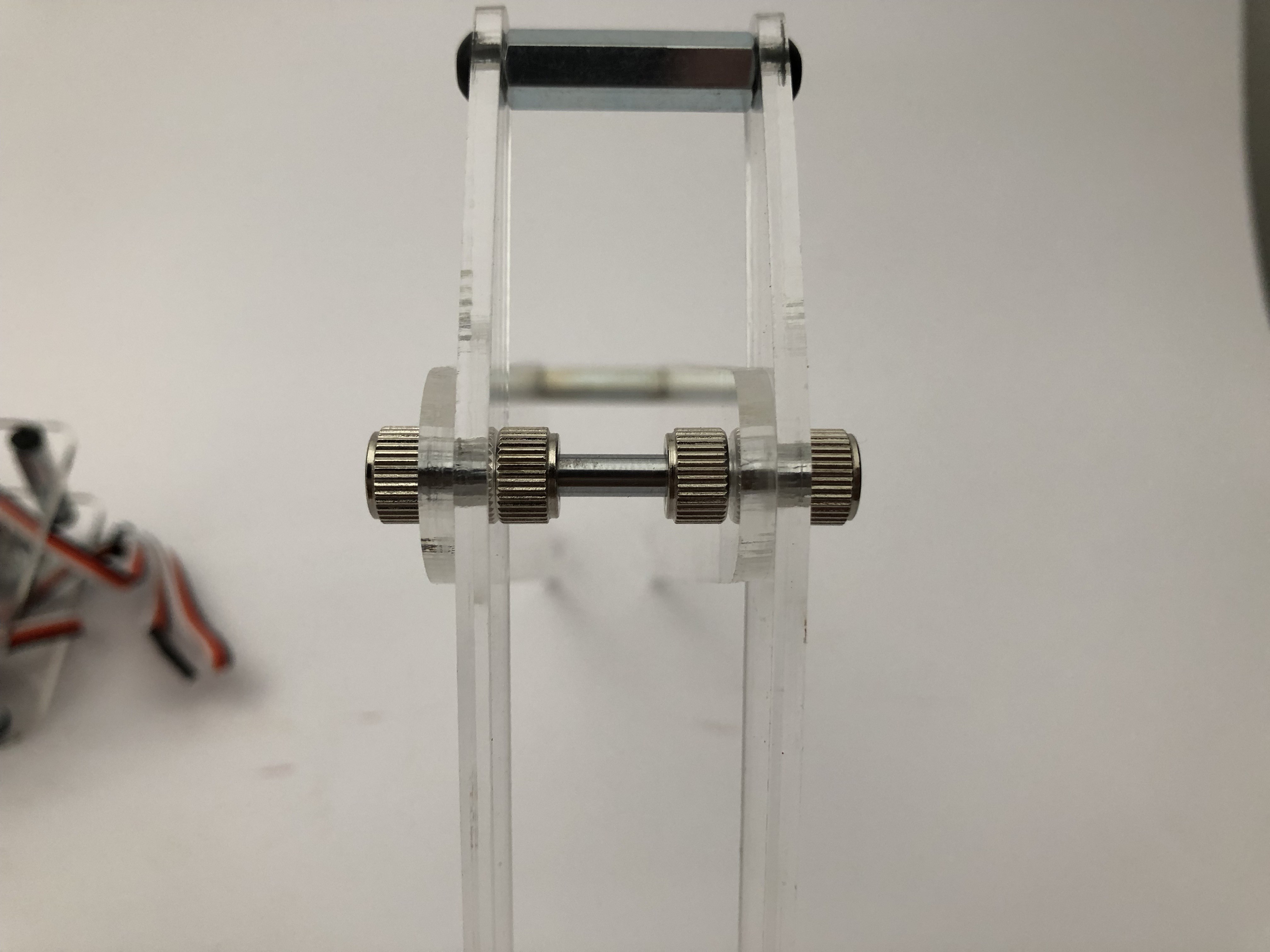
I'm using 4mm shaft collars for the joint. Nothing fancy at this point. No bearing(s):
3rd issue (3rd? I've lost count):
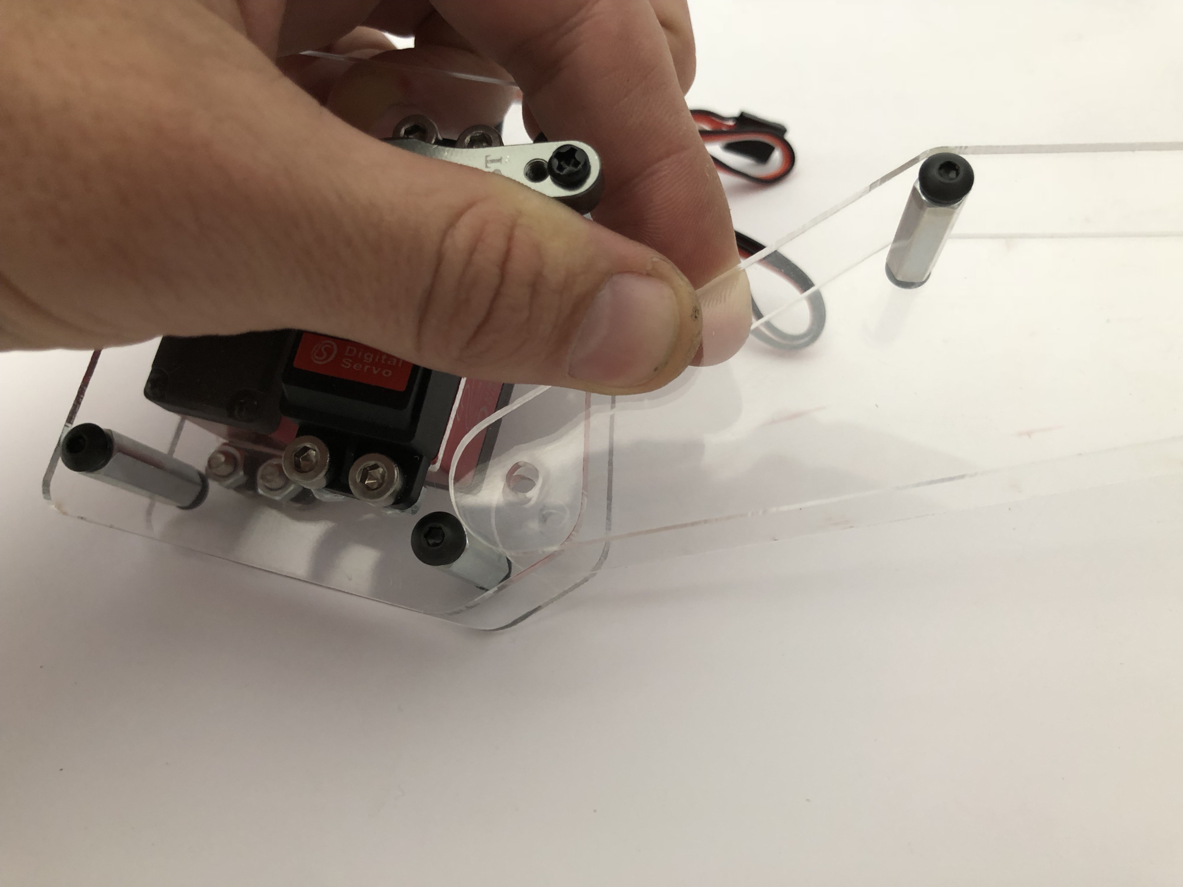
The 4th standoff support is too close to the joint. I removed it. I don't actually think it's necessary since the shaft itself is fairly rigid.
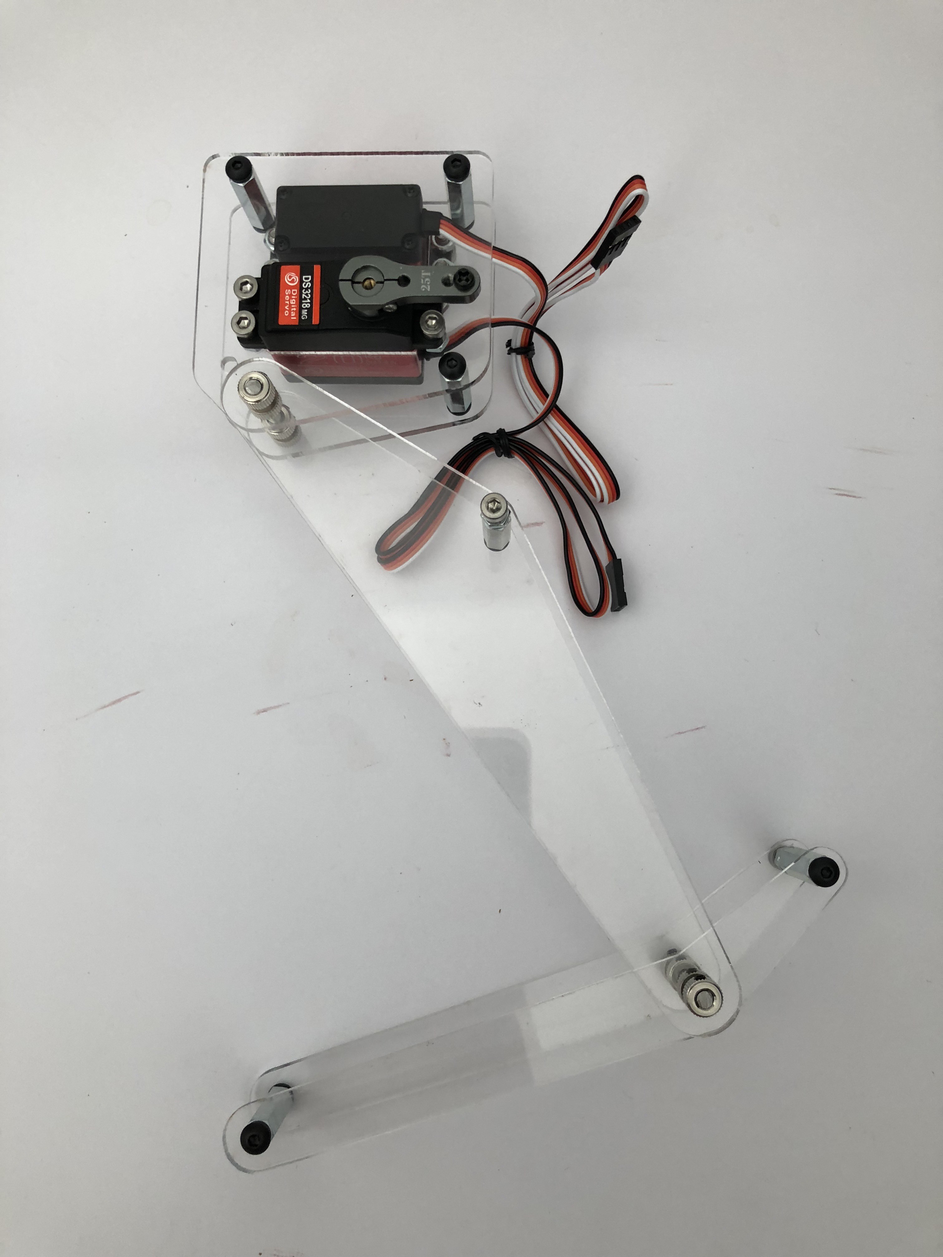
Femur attached:
I have not idea how to create the link between the servo horn and the femur yet. Ball joint? It needs to be rigid...
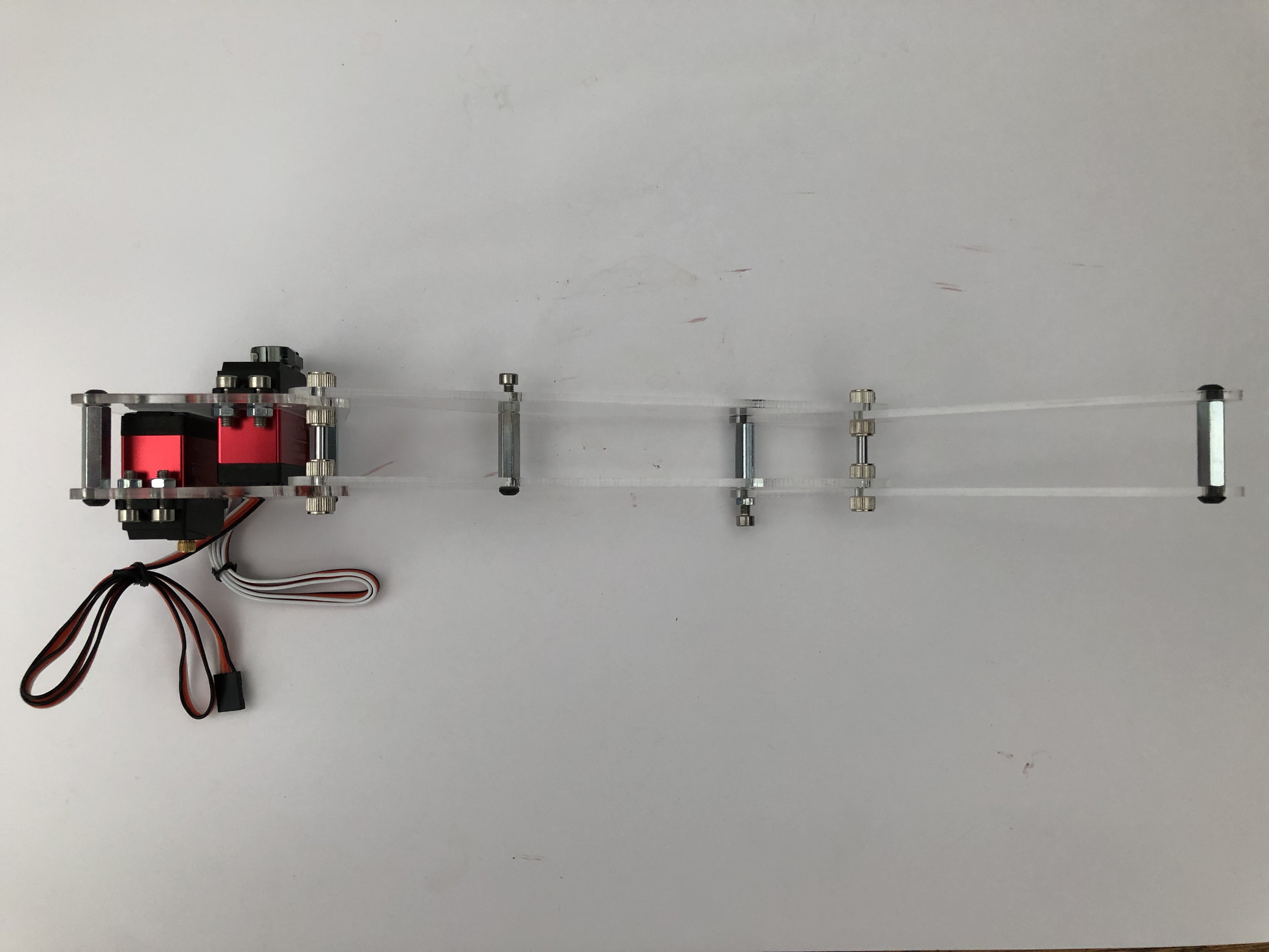
Tibia:
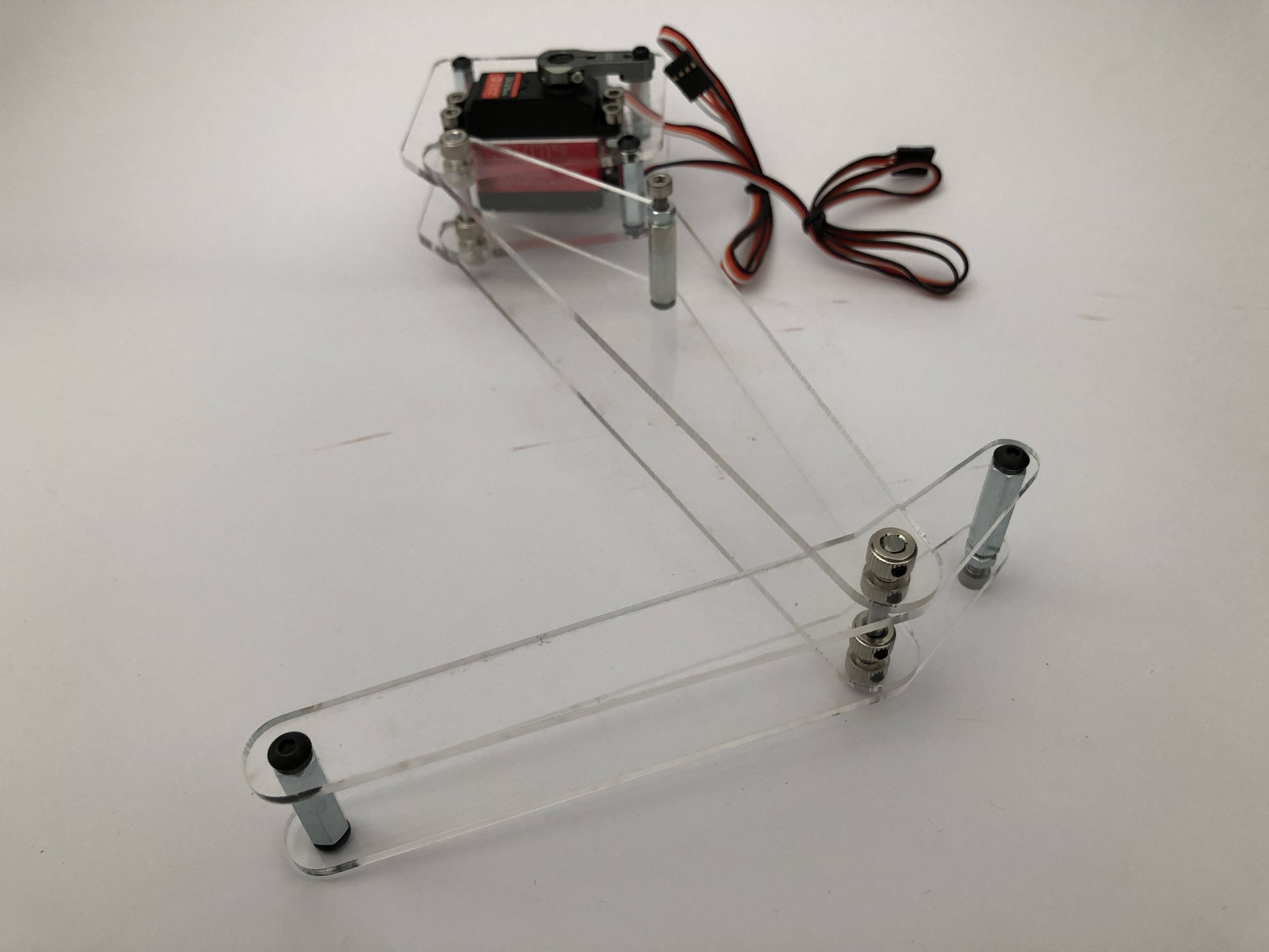
Front and right views:
I'm pretty satisfied with this, considering it's the very first iteration. As soon as I've made a plan with the linkages I'll put an Arduino onto it for a bit of a demo.
Please add questions and suggestions if you have any!
Woof.
Discussions
Become a Hackaday.io Member
Create an account to leave a comment. Already have an account? Log In.