 ober
ober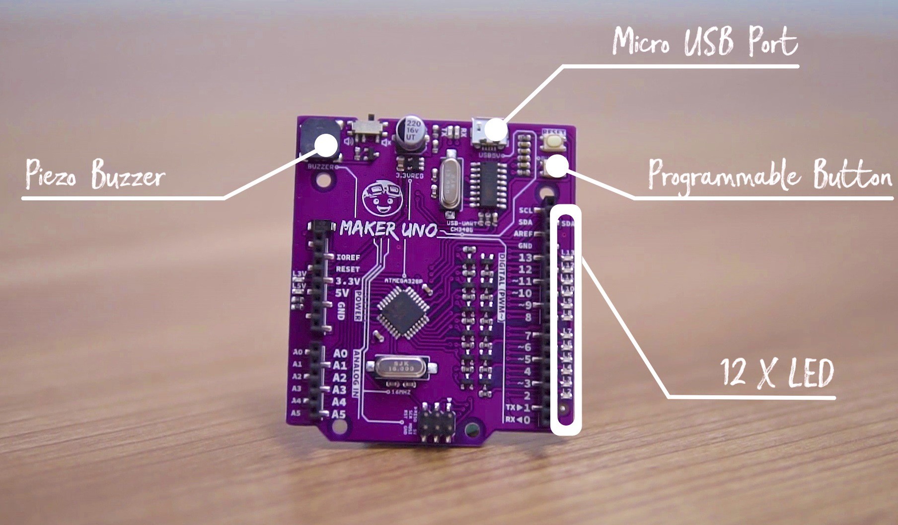
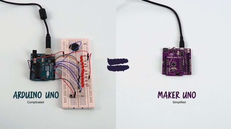
The buzzer/audio output is so useful, why Arduino does not come with pre-build buzzer? Why use USB B type that is rarely being used (only on USB printer). Can we utilize the USB MicroB cable which is commonly being used on power bank charger, and most of the Android phone?
Of course there are other feedbacks too, e.g.:
- More Flash memory
- Faster processing speed
- MicroSD socket
- WiFi and BLE
- More IO, expansion maybe?
- More ADC input
- More PWM output
- More UART (especially hardware UART)
From here, we decided to re-designe and produce an Arduino UNO compatible board that is suitable for students and beginners. An Arduino UNO which is better choice for education.
The objectives:
- It must be affordable for students. You might think USD 22.00 is affordable, but for some parts of the world, this figure is still considered a privilege, a luxury. It must be lower than USD10.00.
- It must be fully compatible in term of using Arduino IDE, Arduino UNO R3's library and example code. This is the most important spec because Arduino.cc have done an amazing work in making the Arduino IDE to work seamlessly on every platform and there are millions of example codes for Arduino UNO R3.
- Friendly enough for teachers and students (that does not have electronics background and fundamentals) to learn microcontroller, coding and electronics.
- Build in the features which is important, even it is basic.
We are familiar with Arduino UNO R3 as we have designed CT-UNO before. But the objective is not to design and produce another low cost Arduino UNO, it is to solve the problems of teacher and student. They wanted to teach electronics, coding and microcontroller; and millions of students wanted to learn this amazing platform. Is an essential tool for makers.
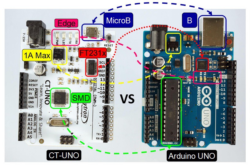
Picture showing CT-UNO (Left) vs Arduino UNO R3 (Right)
Before we can start the development, there are a few features and spec that need to be finalized. So here is it.
Which MCU? The Atmega328P or 328PB or even Atmega32U4?
1st, the MCU, we look into Atmega328PB, tested it with our first prototype and there are some findings that stopped us from using it :(
- Atmega328PB is not fully compatible with Atmega328P which is used on Arduino UNO R3.
- The hardware (Pin assignment, flash, memory, operating voltage, etc) is compatible, but the registers are not. Therefore, the sample codes of Arduino UNO R3 are not compatible.
- Bootloader is not fully compatible too, there are some tweaking needed.
- Arduino IDE does not fully recognize Atmega328PB as Arduino/Genuino UNO, therefore, you cannot simply modify the library to carter for the register changes and click the upload icon on Arduino IDE. The sketch can be compiled successfully, but Arduino IDE will fail to download the code into Arduino board with Atmega328PB.
With that, we decided to stick with Atmega328P which is fully compatible with Arduino/Genuino UNO R3. Keeping the simplicity and reduce the confusion and risk for beginner which likely are students :) BTW, we do note that Atmega328PB is way better MCU for next Arduino UNO board, it provides:
- 2 x UART (hardware)
- 2 x I2C
- 2 x SPI
- 2 more 16-bit Timer/Counter
- 10 x PWMs instead of 6 x PWMs on Atmega328P
- And not to forget the capacitive touch peripheral
- Not to mention that the price of Atmega328PB is slightly lower that Atmega328P
Even Hackaday wrote about Atmega328PB when it is released in early of 2016.
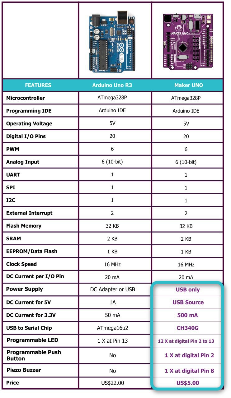
The above table lists the comparison between Arduino UNO R3 vs Maker-UNO. The USD5.00 price is offer during kickstarter campaign: http://makeruno.com.my/kickstarter. The retail price is USD6.00.
How about Atmega32U4 on board Arduino Leonardo? Two main concerns in using this powerful MCU on new Arduino compatible board:
- Atmega32U4 is way more expensive vs Atmega328P, and to democratize this controller board further, we need to ensure the cost is affordable.
- Arduino Leonardo is not as popular Arduino UNO. There are millions of example code and training material based on Arduino UNO, it goes back to friendliness for beginner.
With that, we decide to use Atmega328P as the controller.
Is USB to Serial needed and which solution?
So is USB to Serial IC needed? Yes, if we are to use Atmega328P, a USB to serial is a must to load program via bootloader from Arduino IDE, and to provide the serial connection for debugging purpose. Or can we make it separate like Arduino Pro 328 from Sparkfun? Nop, it should be built-in on board for beginner, as the name of Arduino PRO 328 says, it is meant for the Professional :) As the objective of Maker-UNO is for beginner, so a USB to Serial IC is needed, but which one? To use FT232, FT231X, CP2102 or CH340G, or other USB to serial IC? We use FT232 and FT231X on several products and it works perfectly and stable. We also started using CH340G, it is a low cost USB to Serial IC that offers quite stable performance at speed up to 115200 bps. We decided to get feedback via real experiment. We build and distribute the 1st prototype to ARUS, our academic partner. They did an amazing work in testing the boards and we managed to get a Blue screen on a Mac OS laptop. But after some investigation and tests, it is due to driver version vs Mac OS version :) It was solved by installing the correct driver version, Yeah! We are Windows users, so CH340G was tested on more than 50 laptops (Windows) in our company and during training. Last but not least, Linux. We use Raspberry Pi (which is Linux based OS) as test jig and each and every Maker-UNO is tested before we ship it! The Raspberry Pi actually test the CH340G by loading test code into the Maker UNO and further load the default code that produce the super mario melody and the LED running when you receive the board :)
The unboxing of Maker UNO
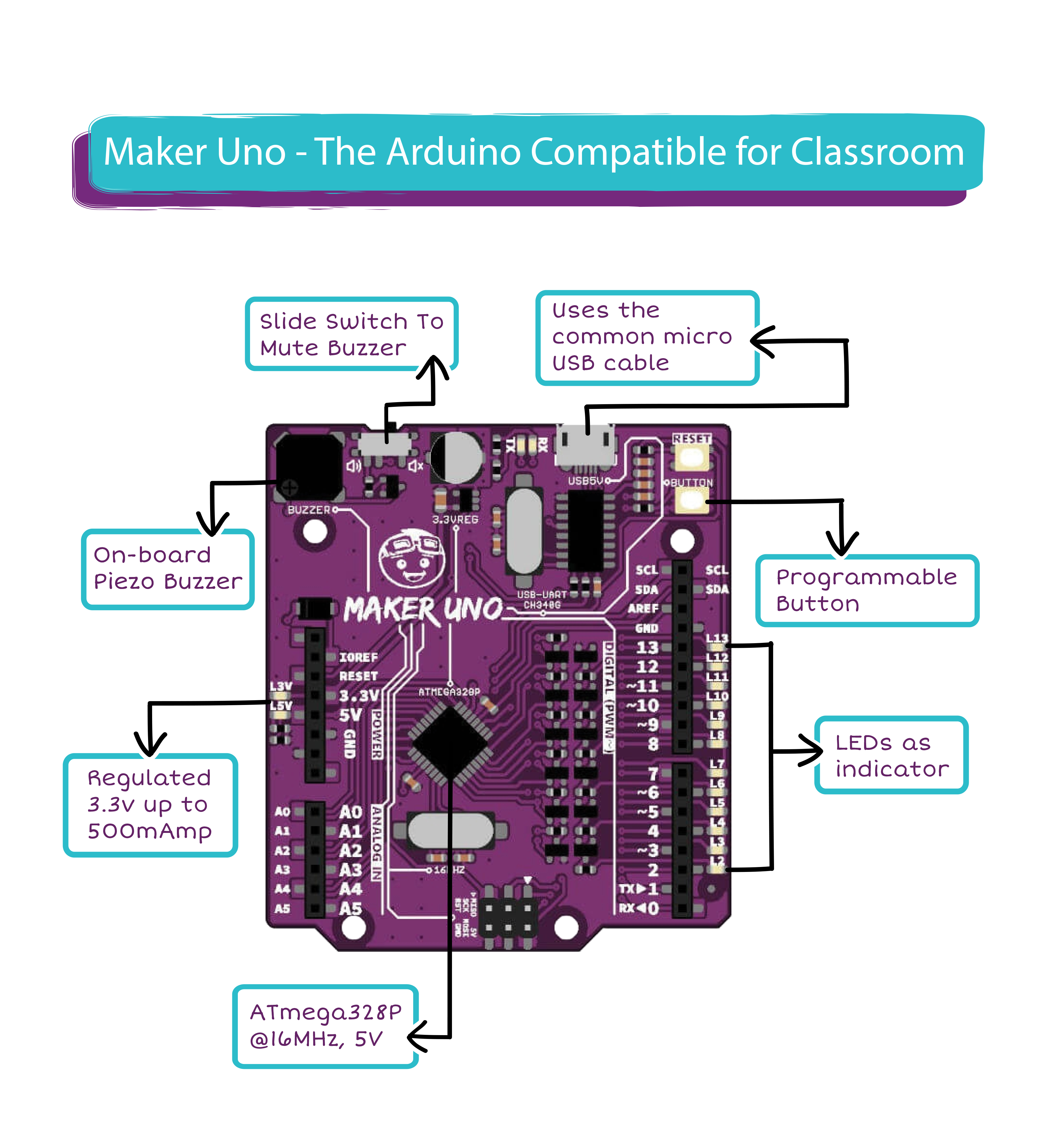
Isn't Buzzer an Awesome Audio Output?
I have always wondered, why wasn't there Arduino board that comes with speaker or buzzer as audio output? At least there is none on the official boards from Arduino.cc. Well, that assumption is over with Maker-UNO. We have decided to add a piezo buzzer for everyone to program and play their favorite melody, learn programming and music at the same time on the same board :) The buzzer is tie to Pin 8 (D8) of Arduino via a slide switch to connect or disconnect it, this is to ensure the full compatibility of Arduino ecosystem. If pin 8 is needed as output or input for other purpose and you do not want the buzzer to buzz, just push the slide switch to disconnect the buzzer. Now, everyone can be a musician. Here is the Christmas song from a Maker-UNO user:
LEDs for Every Digital Pin
We all agreed that LED is the good output indicator, it can indicate HIGH or LOW, and even Analog output from PWM. It is very useful during basic troubleshooting; is your program really giving HIGH or LOW logic? Why is the program not working? Or is the circuit not working? Well, an LED for every digital seem to be useful, right? And why not? LED is low cost enough. So we decided to add a LED for every digital pin on Maker-UNO. But how should the connection be? As easy as normal active high LED series with resistor? Maybe, so the 1st prototype of Maker UNO has 12 LEDs, series with 1K Ohm resistor in active high configuration, from pin 2 to pin 13. Tested in the field by our engineers and ARUS teachers. The feedback? Not really encouraging :( The 1K ohm resistor will affect the input voltage if the pin is configured as input and pull-up. It becomes voltage divider and affect the logic voltage. So we need to have a circuit that is able to drive the LED but will not affect the operation of digital input or output. We decided to use MOSFET to drive LED:
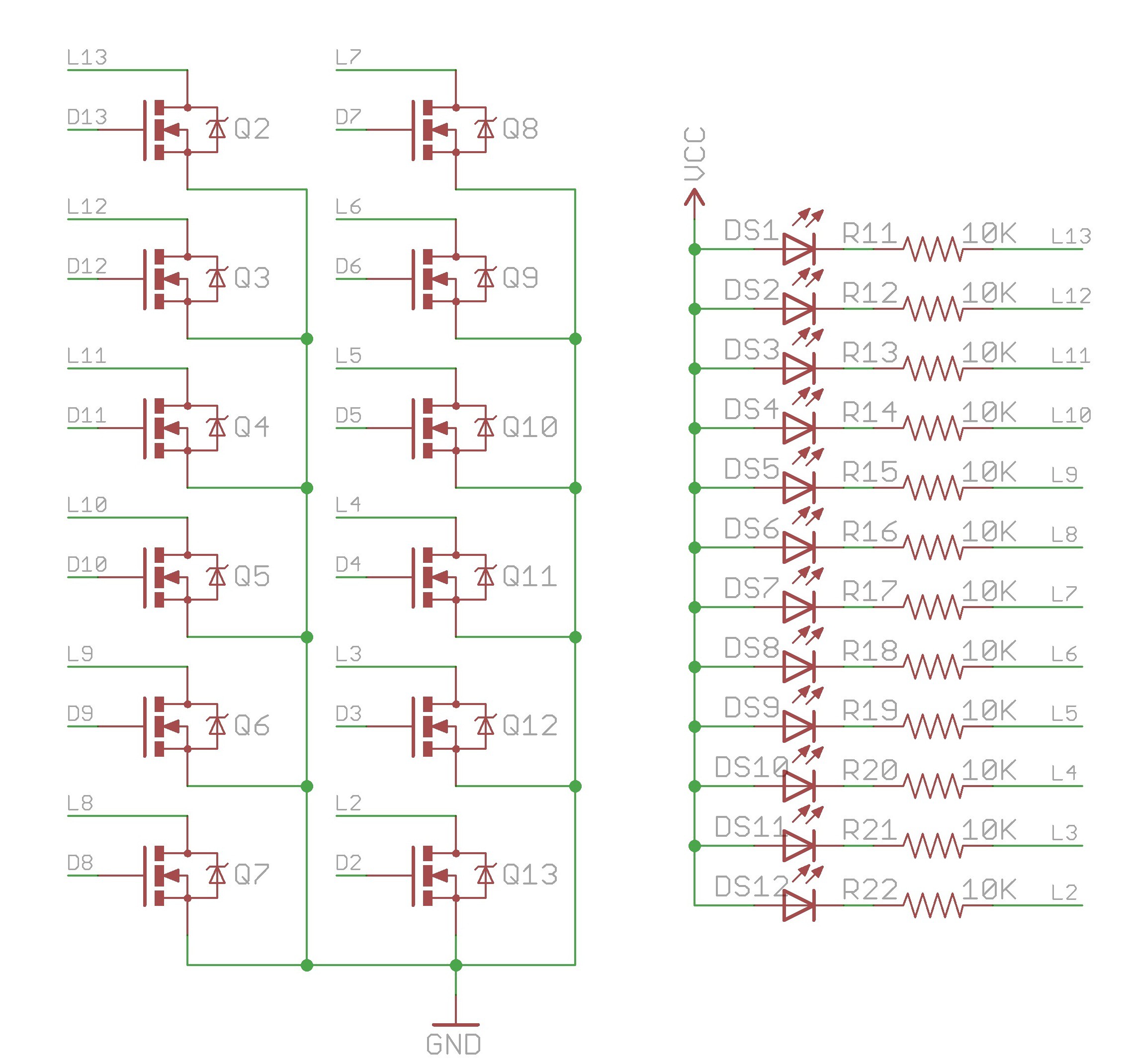
This is the interface of LED indicator for each digital pin from Pin 2 (D2) to pin 13 (D13), Pin 0 (D0) and Pin 1 (D1) are serial pin and the indicator is at the top of Maker UNO, next to microB USB socket. With this interface, it will not interfere the operation of digital input or output :) And we do know that if the pin is configured as digital input, the LED might illuminate by itself as the input is floating and MOSFET might pick up environmental noise and activate the LED, yet this does not affect the operation. On the other hand, we are creating Maker UNO board manager package and might modify the optiboot to fix this uncertain LED state. As of May 2018, after gathering feedback from kickstarter backers and educators, we decided to upgrade maker UNO to Rev1.1 which solve the noise illuminating indicator LED problem. Check out the update at the bottom of this project. With 12 LEDs in a row, you can actually do POV and save many hours to setup and program a running light.
Built in Digital Input
Again, input is very important in learning coding and microcontroller, it provides the mechanism for us as human to interface with our program or Arduino. It also provides the channel for microcontroller to grab information from various sensor, further react to its environment. A built in push button will provides a simple and straight forward method for beginner to learn about digital input. Therefore we decided to add a push button at Pin 2 (D2). Yet, to ensure this push button (permanently connect to Pin 2) does not affect the operation of this pin (digital input, digital output, software serial); there is no pull-up resistor nor pull-down resistor, but there is a 1K ohm resistor connected in series.
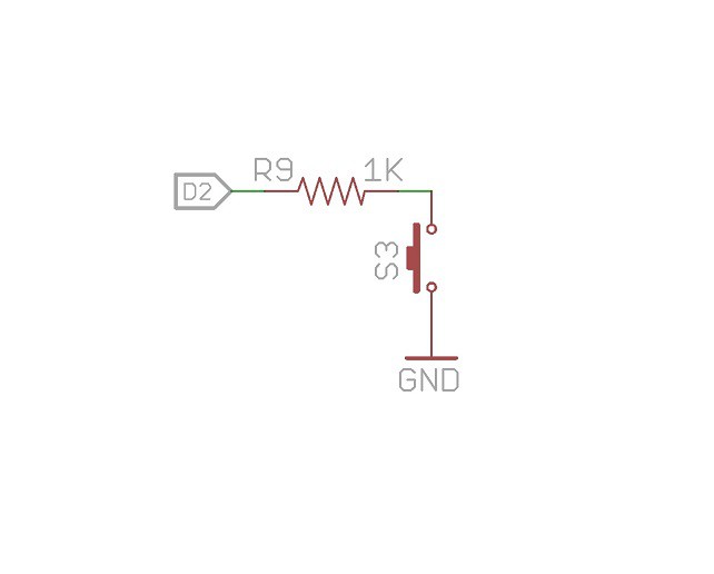
Of course, to use a push button properly, there should be pull-up or pull-down resistor, ensuring the default state. With this connection, we need pull-up resistor! Well, Atmega328P provides option to enable internal weak pull up on every IO. so we can utilize that. By adding this code in your sketch:
pinMode(2, INPUT_PULLUP);
And hey! Arduino IDE comes with example of digital input at Pin 2. Files-> Examples-> 02.Digital -> DigitalInputPullup!
99% compatible with Arduino UNO R3
We cannot claim 100% compatible despite all the efforts :) We have removed the DC jack for DC 12V adapter, and of course the 5V voltage regulator. So the default method to power Maker-UNO is via the USB microB cable, it can comes from power bank, charger, and even Raspberry Pi power supply :) Of course when Maker-UNO is connected to computer/laptop to load program too, it is powered. It is obvious benefit to remove the DC jack and 5V regulator because if you look at the projects using Arduino, 12V (Vin) is rarely being utilize and during training, the 12V adapter is not in the kit at all. With that, we cannot claim it is 100% compatible with Arduino UNO R3. Shield that requires Vin to be powered such as some GPRS shield, is not compatible with Maker UNO. But all the code in Arduino IDE for Arduino UNO is fully compatible for Maker-UNO.
It might seem simple improvements. Just by adding a buzzer, LEDs, push button, replace USB B to USB MicroB, replace USB to Serial IC and removed DC jack + 5V regulator. Yet, we believe these modifications will help the educators and beginners.
Last but not least, to democratize further the education of microcontroller, electronics and coding to the masses, we make it as affordable as possible. Maker UNO is being offered at USD6.00 only. Please visit the official site of Maker UNO: http://makeruno.com.my/
Feedback to improve Maker UNO is more than welcome.
Maker UNO Rev1.1
With feedback gathered during Kickstarter campaign we decided to fix the random LED illuminating when the pin is configured as input (default). There is a simple solution to this problem (thanks to our kickstarter backers). By adding a pull-low resistor to each digital pin will prevent the N-MOS's gate from picking up noise when the pin is in input state. Yet to avoid this pull-low resistor affecting interface that have pull-high resistor such as NPN output (Open drain) from some sensors, we need to ensure the value of resistor is high enough, and of course experiment need to be carried out. The objectives of this additional pull-low resistor are:
- Discharge the noise from pin when it is configured as input, preventing it from floating further preventing the LED to be activated randomly.
- Avoid affecting any other external interface such as NPN output from sensor
- Do not introduce other interface problem, if unavoidable, we will need to address it.
With that, we have decided to source resistor with the value from 1Mega Ohm to 100Mega Ohm. And we notice huge resistance is not common in SMD size resistor (0603 - Imperial), yet we manage to assemble Rev1.1 protoype with (pull-low resistor for digital pin):
- 1M Ohm
- 3M3 Ohm
- 5M1 Ohm
- 6M8 Ohm
- 10M Ohm
- 20M Ohm
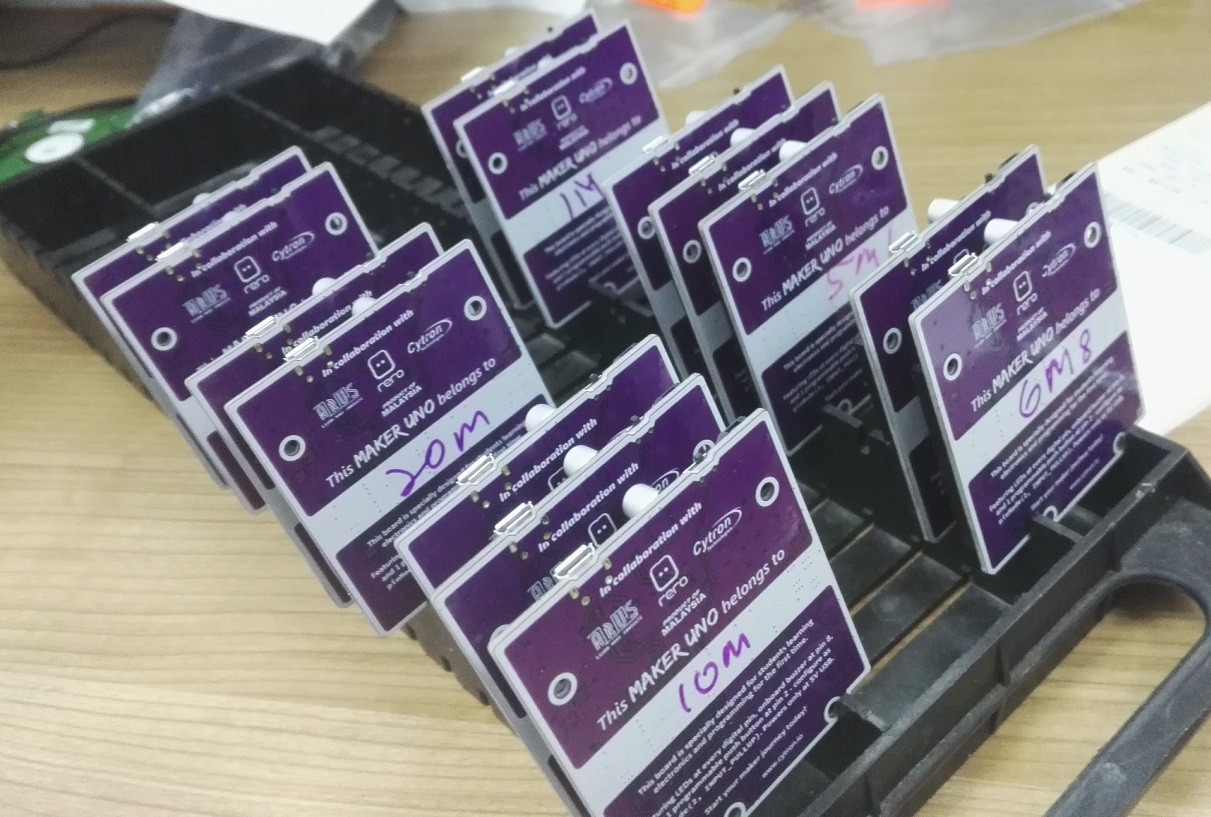
Picture shows partial of Maker UNO Rev1.1 prototype boards. With the additional pull-low resistor, no random LED illuminating anymore. But which resistor value to use? Most of pull-up resistor uses are 5K Ohm to 100K Ohm for NPN sensor, so 1M Ohm pull-low resistor will still be able to offer sufficient voltage level for Atmega328 digital pin to detect as logic high. Of course the higher value of pull-low resistor the better, but we do not want to create another problem where the noise cannot be discharge properly (the main purpose). And we have also identify application that uses high resistance to interface - capacitive touch. If you check Arduino Capsense library (Playground), the recommended resistor for Capsense is 100K Ohm to 50M Ohm. We carry out capacitive sense experiment with all the Maker-UNO Rev1.1 prototypes and notice:
- Resistance for Capsense's resistor cannot be bigger than or equal with the pull-low resistor.
- Resistance for Capsense's resistor must be half of the Resistance for pull-low resistor to get a good Capsensing result.
That's not good because in the library, up to 50M Ohm of resistor can be used. We need to use 100M Ohm for pull-low in that case :( Nonetheless, we did found out that with resistance 5M1 Ohm and higher, the indicator LED will illuminate if user accidentally touches/rubs the digital pin :(
So after many tests and discussion, we decided to use 3M3 Ohm resistor as the pull-low resistor :) And we recommend using 1M Ohm resistor for Capsense experiment, as suggested in official Arduino starter kit.
What else?
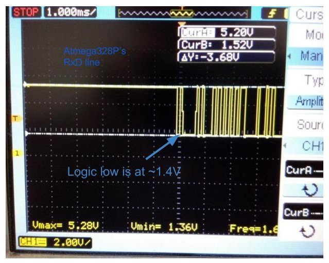
Since it comes to Rev1.1, we should improve it to be better :) Besides the additional pull-low resistor modification, we did more experiments with the hope to get more findings. We did get one, in Rev1.0, there are two indicator LEDs for TxD and RxD of USB to Serial line. These LEDs are connected directly to the hardware UART line of Atmega328P and CH340G (crossed connected). It works! However, we do notice that by adding these LEDs and with the 1K Ohm series resistor between Atmega328P's pin and CH340G, it affects the communication of CH340G with external devices. In some applications, especially for armature user, the on board USB to Serial can be utilized as bridge for computer to communicate with other devices besides Atmega328P (even it is permanently connected). There have been many examples of utilizing this IC. A good example is to use Arduino board to configure Bluetooth module, HC06, from computer serial terminal. This is seldom being utilized, but we noticed with the indicator LED at Atmega328P's RxD pin, CH340G's TxD voltage (logic) is being divided by the LED and 1K Ohm resistor (in series). When CH340G transmit data from computer, there will be logic high and low (that is what serial communication do). Logic high is working as expected, but logic low is not good. Using oscilloscope to probe the RxD line of Atmega328P (or TxD of CH340G), we notice the logic low voltage is around 1.4V. For some devices, 1.4V is not low enough to be detected as logic low or 0. For Atmega328P and most of the shields that we have tested, it is working fine. But for HC06, it is not :(
Not to worry, we have also figure out and tested the new solution. We increase the resistance of LED's resistor to 10K Ohm and get very good result of 0.6V (logic low), and the 10K Ohm resistor does not affect much on the brightness of indicator LED. To further make it better, we decided to move the indicator LED to CH340G's TxD pin before 1K Ohm series resistor.
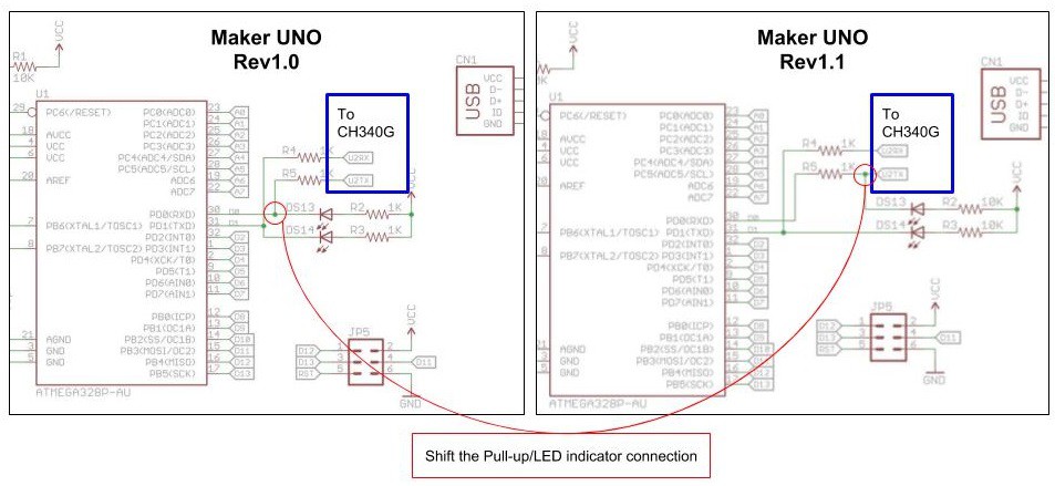
The schematic shows the connection shifted and the resistor value changes. Now, the Rx and Tx signal is at very good level to be detected at logic high and low respectively. And there should be no problem for both USB to UART IC and Atmega328P to communicate with external devices.
Sounds good, anything else that have been improved? Well, the last improvement that we can highlight but not really significant is the piezo buzzer. We have move the VCC/Power of buzzer to 3.3V instead of 5V (Rev1.0).
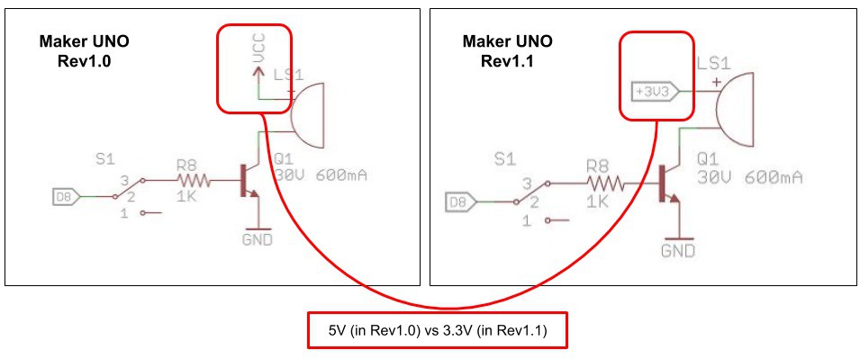
With lower voltage, we hope to prolong the life span of buzzer, although we yet to see any buzzer fail from the beta released up to the date this is written.
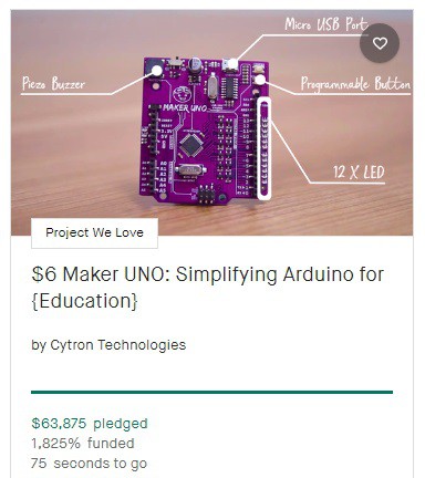
With this, we would like to thanks every teacher, educator, student, beginner, Arduino.cc and backer in kickstarter campaign. The project was 1825% funded.
Summary
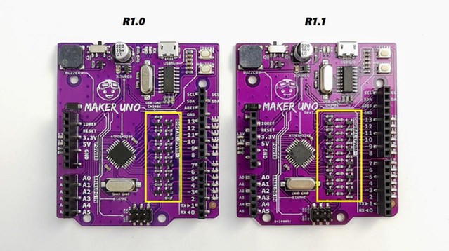
At the time this article is written, we have shipped out package to backers that choose Maker UNO Rev1.0. Maker UNO Rev1.1 will be assembled and test next week (early of June 2018) by our production team. Here are the changes we made on Maker Rev1.1:
- Additional 3M3 Ohm pull-low resistor for every digital pin (D2 to D13) to discharge environmental noise and ensure the indicator LED (Blue) will not illuminate randomly.
- Increase the pull-low resistance LED indicator for RX and TX line from 1K Ohm to 10K Ohm, and shift the LED indicator to Atmega328P's RxD to improve the UART logic voltage level.
- Power the piezo buzzer with 3.3V instead of 5.0V in the hope to prolong the life span of buzzer.
- Last but not least, "Rev1.1" label is added to differentiate the board, right under "Maker UNO" label.