 Dave Vandenbout
Over the past few weeks, I've done two things related to his project:
- Wrote a plugin for KiCad's PCBNEW that lets you paint pads of specific types.
- Prototyped a vertical HDMI connector and decided it wasn't worth it.
Pad Painter
When you're dealing with FPGAs having several hundred or more pins, most of which are interchangeable, it can be perplexing when trying to choose the correct pin to connect to some other peripheral. You want to choose one that's close to where it will be connected, but you also need to make sure it's the right type (don't connect an FPGA VCC pin to an HDMI connector data pin), and it's in the right I/O bank. I wrote the PadPainter plugin for KiCad to highlight pads of ICs that meet a set of conditions such as the electrical function (input, output, bidirectional, etc.) and the bank (or unit) to which its assigned. This tool quickly shows me the pins of the FPGA which are candidates for connection to other peripherals. If you're dealing with large FPGAs or SOCs, this tool may also be useful to you. You can read more about it here.
Vertical HDMI Connector
I decided to replace the SATA connectors on the original CAT Board with an HDMI port. Because of its location, the normal right-angle HDMI connector would be blocked by the USB ports of the Raspberry Pi. So I decided to use a vertical connector.
Finding vertical HDMI connectors wasn't easy. Digikey and Mouser didn't have any. I finally found some on Aliexpress, but I had to piece together the footprint dimensions from several sources. Obviously, I couldn't really trust my footprint so I built a small prototype board using several hole sizes and trace/space widths:
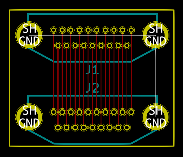
The PCB showed my footprint would work with the vertical HDMI connector:
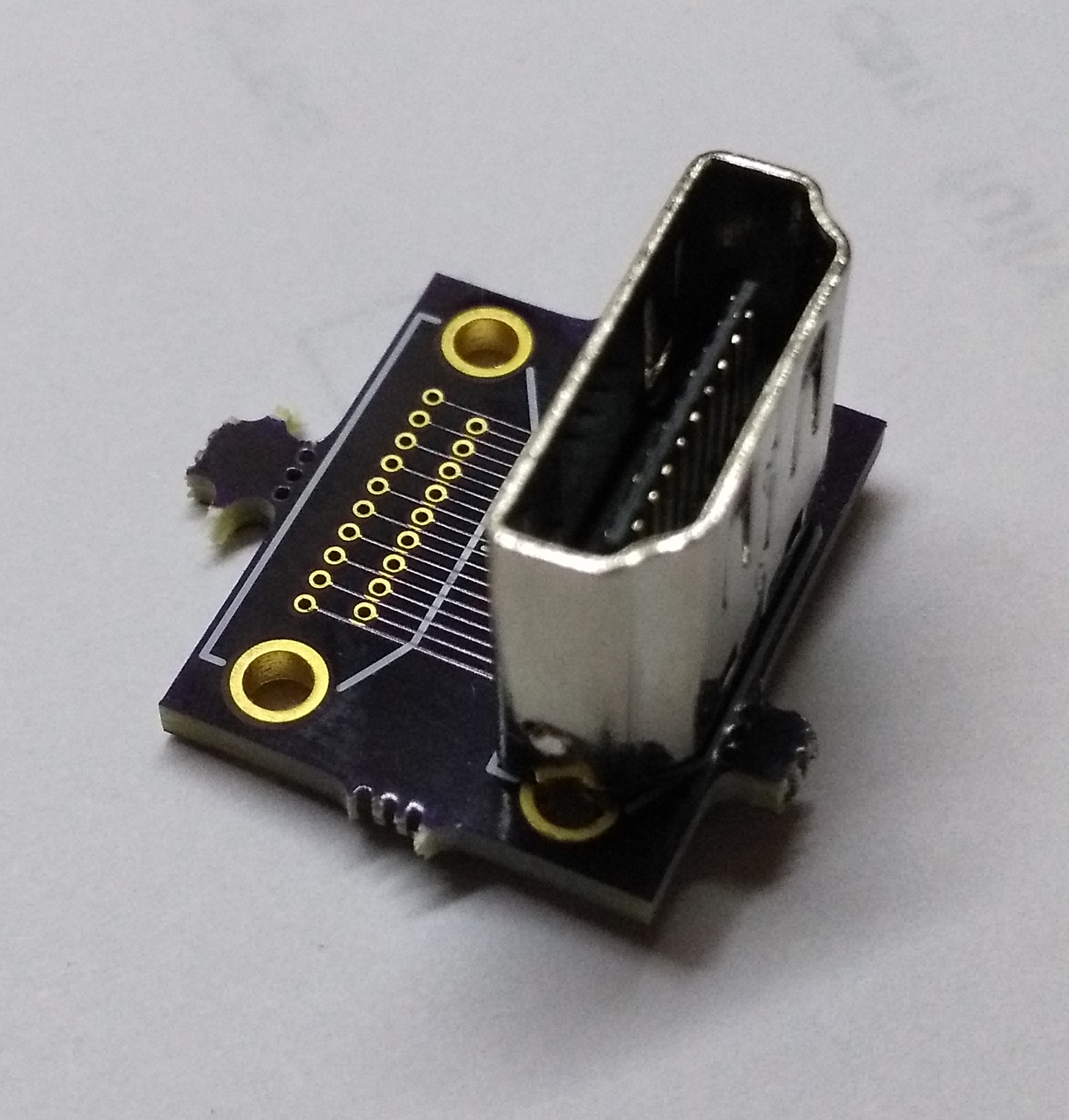
Even so, I decided not to pursue this any further. The choice of suppliers for the connector was too limited and sketchy, and the assembly process looked like bent pins would be a problem.
Instead, I'll use the more common right-angle HDMI connector and bring it off the same side of the PCB that's used by the Raspberry Pi GPIO connector. To make room, I'll need to replace the through-hole GPIO socket with an SMT version.
Discussions
Become a Hackaday.io Member
Create an account to leave a comment. Already have an account? Log In.