 David Scholten
Sorry it's been a while, the project is still underway!
Aside from the input/output connectors, the schematic is completely finished (I know this is true this time because the layout is almost finished).
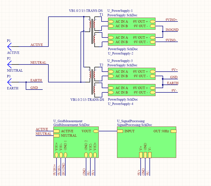
The schematic overview remains the same (minus a couple of mistakes with the power orientation):
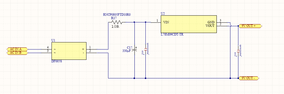
The power supplies are also unchanged (but now the wires are actually connecting and not maintaining an illusion):
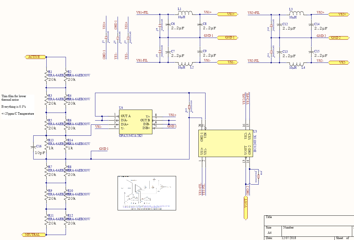
The grid measurement section now contains a new input filtering capacitor (30MHz crossover):
Now, onto the actual changes... The most notable change is that the signal processing portion of the circuit has been significantly simplified to eliminate the 500Hz harmonic filter.
The original intention of this filter was to increase the dynamic range of the harmonic measurements as the available audio range is about +/- 450mV. If the harmonics are only a small portion of the 50Hz fundamental waveform, they will be at the mercy of the sound card's sampling accuracy. The secondary "harmonics only" output would eliminate the 50Hz fundamental component and allow amplification of the harmonics without the 50Hz clipping. This would then be fed to the sound card as a +/- 450mV signal to increase the dynamic range.
However, I eventually decided against this as the filter's response wasn't completely flat - Especially in the more interesting 500Hz-2kHz (10th-40th harmonics) range. Not to mention the sub-500Hz is completely gone (2nd-9th harmonic). It all seemed a bit pointless in the end.
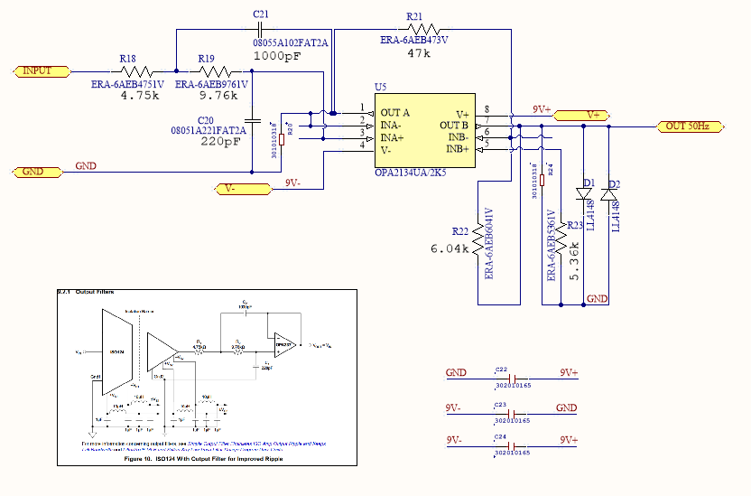
The other change is the removal of the DC-offset removal capacitors from the op-amp U5. As the gain at this stage is 0.129 (as opposed to a value over 1.0), the DC offest from the previous stage (the ISO124's massive 20mV) is reduced to 2.57mV. As the OPA2134 will add not much more than 1-2mV, the final DC-offset will be around 5mV max in most circumstances. This is about 1% of the signal peak, which is reasonable considering sound cards block DC voltages anyway.
Now, taking these changes into account (and the existing design) the final frequency response is flat from 0Hz-20kHz and then decays from after that until about 50kHz where it drops off rapidly.
Stay tuned for the layout pics!
Discussions
Become a Hackaday.io Member
Create an account to leave a comment. Already have an account? Log In.