 jaromir.sukuba
Look at my PCB, look
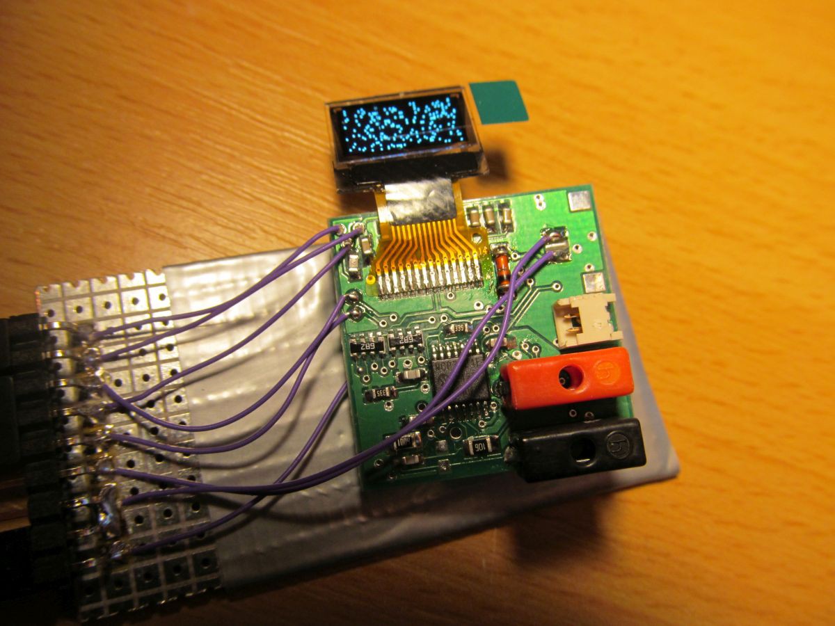
For easier manipulation/programming work I soldered pinheader and a few wires to piece of universal PCB. The progmeter PCB with components is so tiny and lightweight that a few 30AWG wires lift it off the base board. For now, I made some basic functionality check - power supply circuits seem to work, MCU is alive and I can program it, display is OK and communicates via I2C, initialization of display works and it displays "noise" form power-on state of display RAM.
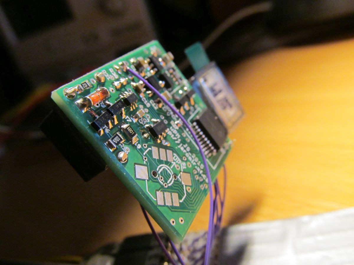 But there isn't everything going just flawless. I found out that the flex ribbon on display is too short to bend over the PCB to get the display panel to other side of PCB, so it is on wrong side for now. The holes for 2mm banana terminals were too small - I had to drill it to larger diameter, losing hole plating material, so soldering the terminals was difficult and I had to glue it in place. I also found out that I2C bus pull-up resistors are connected to analog supply instead of digital 3V3 net, so the I2C debugging was quite confusing. Fortunately, it seems that all the problems can be fixed relatively easy. Yet I have to check the ADC and analog parts, then I'll proceed to PCB ver 1.1
Discussions
Become a Hackaday.io Member
Create an account to leave a comment. Already have an account? Log In.