 jaromir.sukuba
After sucess with digital part of the circuit, I tried to play with the analog too, not that successful, though.
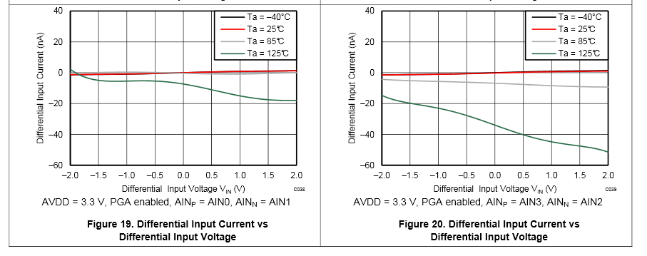
At the voltage measurment mode - MUX2 and MUX3 signals high see schematics - I applied voltage 4V at input terminals and measured voltage across R4. Considering the R4 value is diminished by 10Mohm (DMM internal resistance) in paralell (=910kOhm), one would assume voltage around 0,33V here. But I measured something slightly under 0,25V, resulting in my genuine confusion. Wait, there is nothing but resistor, capacitor and... ADC. Yep, ADC. But hey, it cant be the ADC contributing with such as huge error, because it has input impedance around 25MOhm, I checked it before. 25MOhm across 1MOhm would bring the measured voltage few percents down, but this is something I could tweak by software calibration (which would be needed anyway) - though now I'm looking at voltage few tens of percents down, which is suspicious. No, It can't be ADC, because I checked it, look:
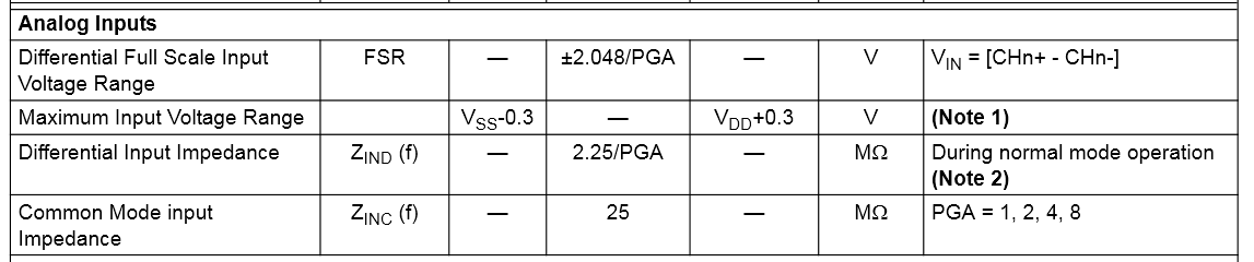
1Mohm, 2,25Mohm and 10Mohm in paralell gives something around 650kOhm, with the 10Mohm upper divider we get to something like 245mV. Close enough to 250mV. I checked voltage across R6 - 1,7V or thereabouts, which is kind of expected. Then I switched active channel from 1 to 3 and voltage on R4 increased to cca 340mV and voltage on R6 jumped to 1V. Confirmed, ADC is doing all the bad things. I used the MCP3424 few times before and was quite confident about it, so I just skimmed through documentation and used it when doing design.

Now, after I found the problem and facepalmed long enough, some solution is expected. I went to mouser and tried to find some other 2-channel ADC with 16- or more bit resolution with acceptable package, here is what I got - not exactly long list. Seems like input impedance around 2Mohm with strong resistive component is common for other ADCs in this class too (like my favourite ADS1100 and similar ones), but ADS1120 looks like something I want.
This ADC has downsides too - I have to sacrifice easy integration via I2C bus and it has only two input channels (compared to MCP3423), so I have to measure the battery voltage via other means. I has SPI interface, requiring 4 wires, along with additional ADC channel for battery measurement it means another five IO pins. Because the battery voltage divider has quite high resistance, connecting to ADC IO pin is problematic, single opamp in voltage follower circuit is needed. My favorite type for this job is MCP6041 - just like in my altimeter or microreader.
So, as I have only one IO pin unused, I have to find 4 more IO pins. There is more ways to solve this problem.
1, Joystick interface takes 5 IO pins, that's luxury for such as slow interface.
- I can save 4 IO pins by using PCA9536 via I2C (which is there for display anyway)
- I can save a few pins by connecting some of joystick pins into resistor network in this manner
2, There is one IO pin taken by charger state monitoring and another one is needed for battery voltage measurement. If I'd use two channel I2C ADC, I can save not just two IO pins, but also opamp. I'm going trade SOT-23 for another SOT-23, but saving IO pins.
3, Use two IO pins I dedicated to in-circuit debugging for something else. Ideally, the ICD pins should be kept free for debugging purposes, but with some care it could be shared for things like user switches or indication LEDs.
4, Using higher pin-count MCU. Most straight-forward solution, but takes precious PCB space.
5, Combination of some methods above.
Not sure about what to use, by now.
Discussions
Become a Hackaday.io Member
Create an account to leave a comment. Already have an account? Log In.