 jaromir.sukuba
So, here it is. As for now, I'm considering this design to be finished and files on github should cover all you need to build one, perhaps with a little bit of help from local project logs.
Accuracy verification
After doing proper calibration against higher-spec multimeter than good old trustworthy DT-830 I made accuracy check of my micro progmeter, using laboratory power supply and UT-61E DMM. UT-61E was connected directly to micro-progmeter and measuring the same value. Here is verification table

where RV is real value (by UT-61E), MV is measured value (by micro progmeter), diff is absolute difference. Diff FS is deviation of full scale value (20V) and diff V is difference of measured value. So, when measuring 1,677V, progmeter displays 1,675V, what is 2mV difference, meaning error approximately 0,01% of full scale or 0,12% of the value.
Using bunch of random resistors I verified the resistance measurement too
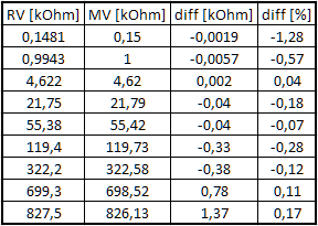
As the full range is virtually unlimited, I calculated only measurement error of the value (this is the worse number). At low ranges (few hundreds of ohms and lower), the accuracy is limited by resolution (0,01kOhm = 10Ohm), but even at 150Ohm it is quite respectable. Higher values doesn't suffer from rounding errors, so the performance looks better.
Current consumption
The current consumption of active progmeter is about 4-6mA, depending on amount of illuminated pixels. After turing off it falls to approximately 60uA. I expected something under 5uA, so 60uA is somehow surprising and honestly I'm not sure where it comes from - perhaps display or ADC. I've got a few clues how to find out, but in the meantime progmeter is fully usable. 60uA would deplete 100mAh accumulator in more than two months, so it you use it from time to time it shouldn't matter much.
Fool-proofness
The progmeter is fool-proof to some degree. Though measurement range is up to 20V, it survives 30V with no problem. Even at resistance measurement range, it survives 30V of either polarity with no problem whatsoever.

On the other hand, except of fool-proofness by design up to 30V, it has no other input protection. If you connect it to 230V AC, it will blow up and ruin your day - this is design decision. Proper protection on such as tiny device is somehow problematic and for checking your microcontroller project not needed, anyway.
Resume
Coming back to goals I set up at the beginning of the project, I'd say it works as I intended. Working on this was a great fun and I learned a few new things - like how to set up project for PIC micro using fully open-source tools. The project is made to be as accessible as possible for anybody, disregarding whether you like to use FOSS tools for flexibility or proprietary tools for convenience.
Discussions
Become a Hackaday.io Member
Create an account to leave a comment. Already have an account? Log In.