 jaromir.sukuba
In one of my previous project logs I had problems with my MCP3424 ADC - it had too high input current - ie. low input impedance, making problems with high impedance voltage divider on input. Now, I've run into problems again.
After doing first crude tests and discovering that it works and really measures voltages and resistances, I got annoyed by huge error near zero voltages or resistances. Higher (more than a few hundreds Ohms) resistances were OK, but short circuit was indicated as something like 100Ohm, that's fishy for sure, so I started to investigate.
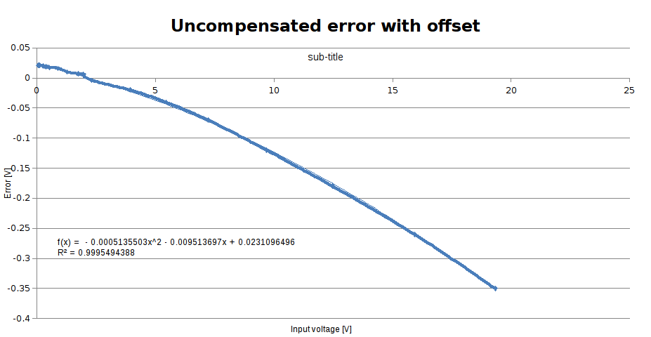
I did manual rough calibration of the device in two dozens of points between 0 and 20V, with somehow more points at the beginning of range:
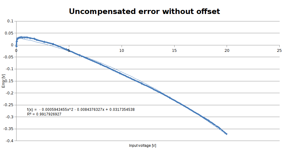
Well error increases almost linearly with input voltage - this looks like input divider isn't exactly accurate, but this could be treated by software calibration as long as the divider and reference voltage is stable, calibration and error correction is something I expected from the beginning. Problem is that the error isn't monotonous function - if you look carefully, it is rising at the very beginning of the curve (low input voltages), then falls slowly down as input voltage rises. Simple quadratic correction does its job, but compensated error is still not that good, especially at low voltages.
Almost 40mV at the beginning of voltage range is a bit too much.
Well, offset rising at low input voltages? That sounds like problem with rail-to-rail input which is never actually rail-to-rail, but requires to be few milivolts above low rail and few milivolts under upper supply rail, but I double-checked the datasheet of ADS1120 and TI states that
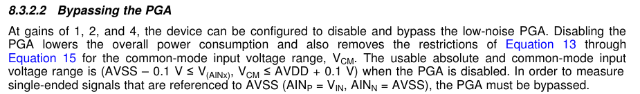
TLDR - once the PGA is disabled (which is my case), the input voltage can safely go to ground level and shouldn't cause any problems. But it somehow does.
Fortunately, when drawing the schematics I had gut feeling that offsetting the negative input probe above ground level could be actually good idea. I reserved two components in the schematics - R12 and R13, one is marked as 0R and another one as DNP - do not populate. In this configuration, negative input is tied to ground.
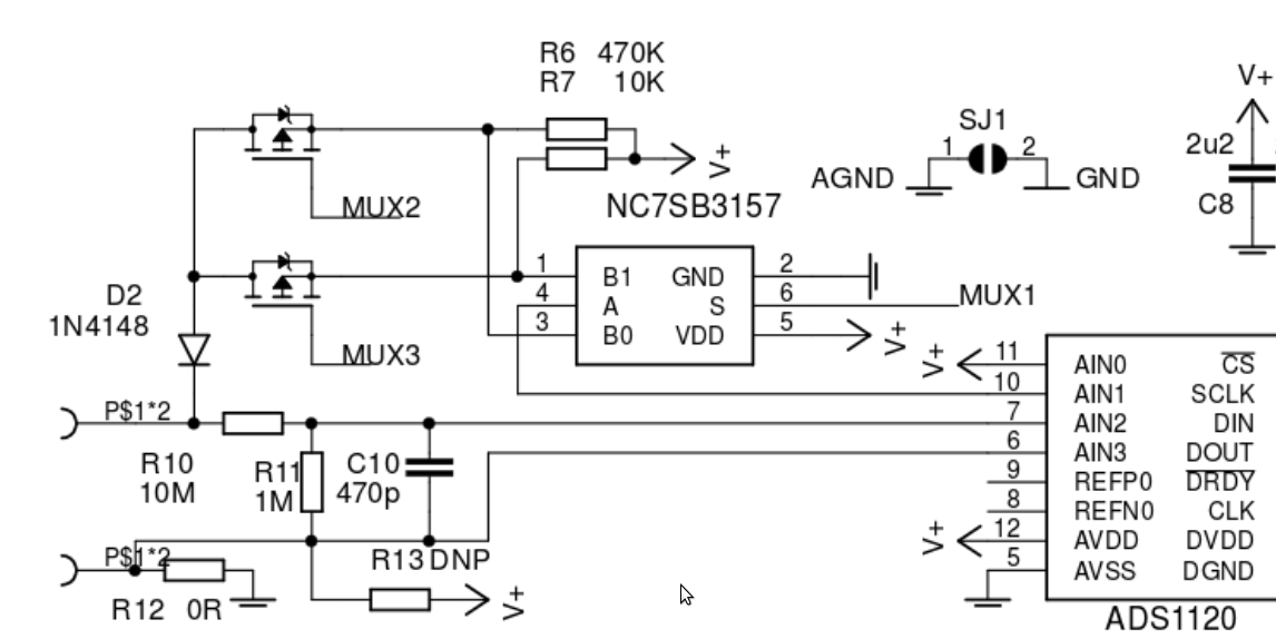
So I removed short circuit on place of R12 and inserted 200 Ohm resistor instead. On R13 position was placed 1k Ohm resistor, creating offset approximately 0,55V on negative input terminal. This offset doesn't directly interfere with measurement accuracy, as the ADC differential input still "percieves" only difference between input terminals. I performed the rough calibration again.
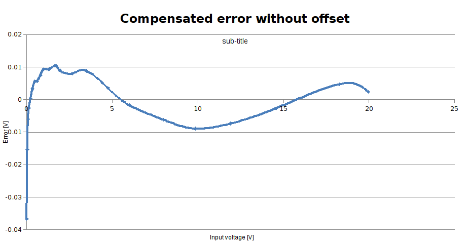
It looks similar to first calibration, but the nasty part at low voltages is completely gone, notice also the reliability factor of quadratic approximation went up from 99,2% to 99,95% and compensated error looks much better
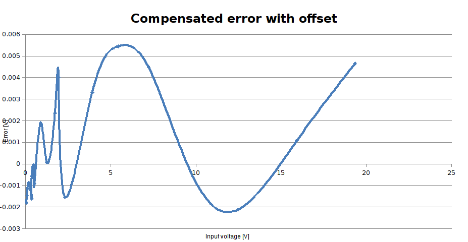
The curve looks more shaky than before, but numbers on Y axis got one more zero in it. Maximum error decreased by almost one order of magnitude and shows no apparent systematic error. The error is now in order of milivolts (on 20V full scale range), and I'm pretty sure my DMM is not up to this task, so I have to obtain something better for more precise calibration. But anyway, even now is the accuracy much better than I expected - thanks to the two resistors.
Oh yes, and influence on resistors measurement accuracy was immediate - the 150Ohm resistor, indicated as something around 240Ohm before, is now absolutely correctly measured as 150Ohm. Nice.
For now, I'm calling this problem solved.
Discussions
Become a Hackaday.io Member
Create an account to leave a comment. Already have an account? Log In.