 jaromir.sukuba
In last days I made some some more progress about firmware, mostly catching tiny bugs and doing clean-up while trying to free up some FLASH memory in order to pack more features into the firmware. I'm really running out of program memory, but it looks like the basic goals I set up at the beginning of the project are finished for now.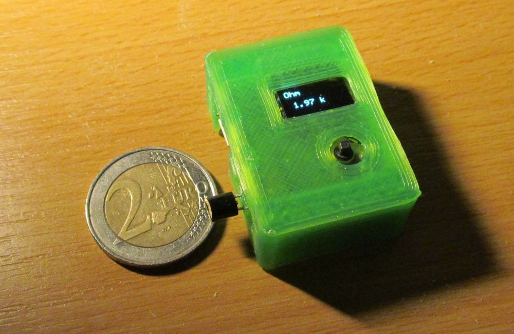
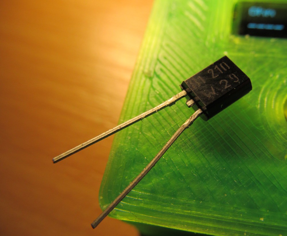
There is KTY81-210 sensor with leads directly inserted into 2mm banana plugs.
In normal measurement mode I can measure its resistance, as expected. The temperature-resistance dependence is in small range fairly linear
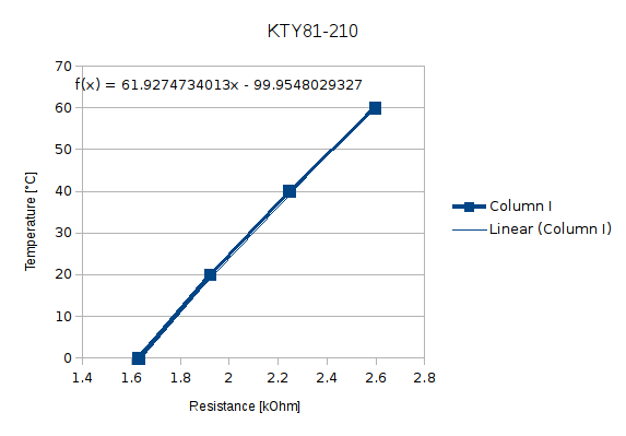
and after entering 0, 61,927 and -99,955 as polynomial calculation parameters into my micro progmeter and switching into calculation mode (note the C indicator) I got temperature result
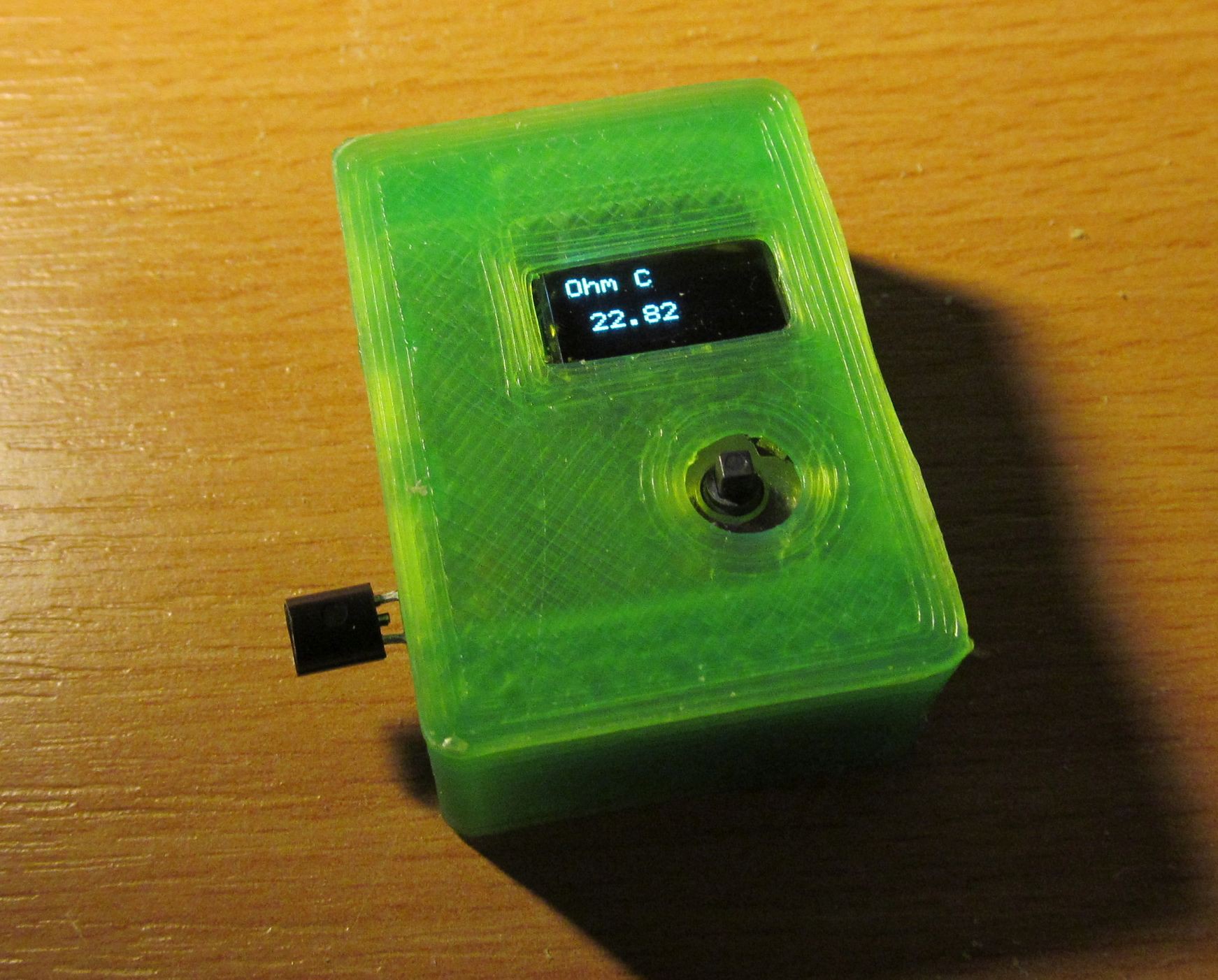
what looks like temperature in my room.
By the way, this enclosure is already second revision. Call me stupid, but the joystick hole is still a bit off, because of my mistake. What more, I feel like the translucent green filament colour is underlining printout defects by poor hotend of my 3D printer, and I ran out of any other colour.
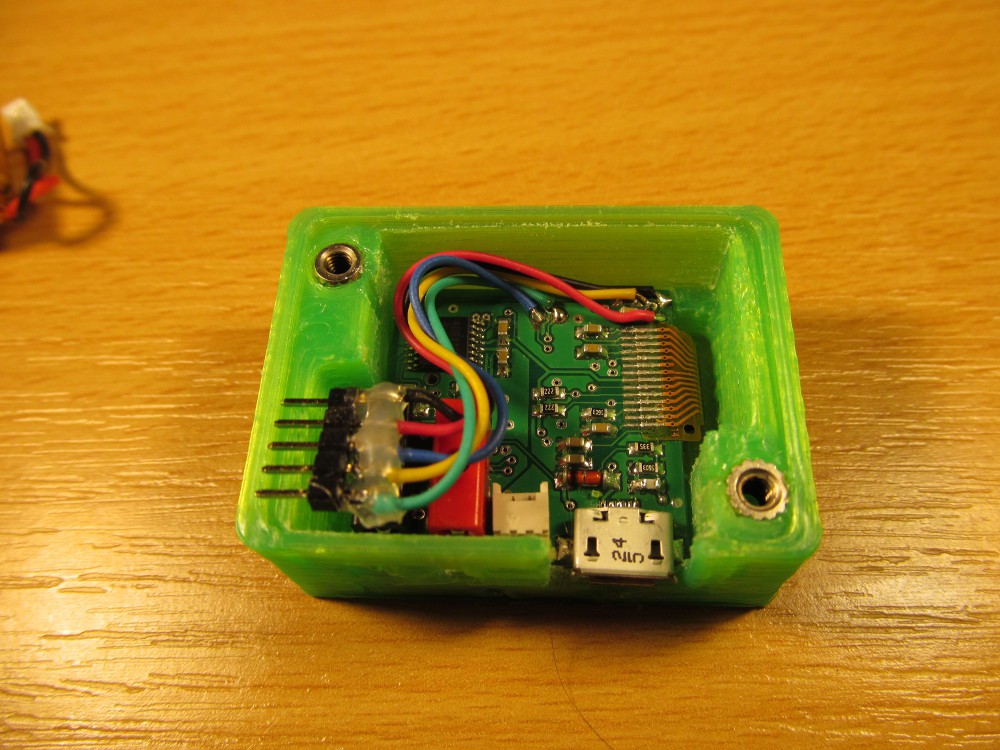
I soldered five wires and 2mm pinhheader (standard 2,54mm is way too big) serving as interim programming connector, but I think leaving it there wouldn't harm anyway.
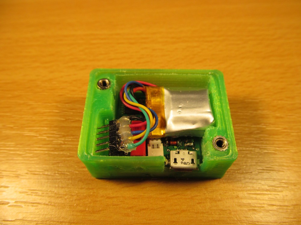
Pretty packed, with battery inside
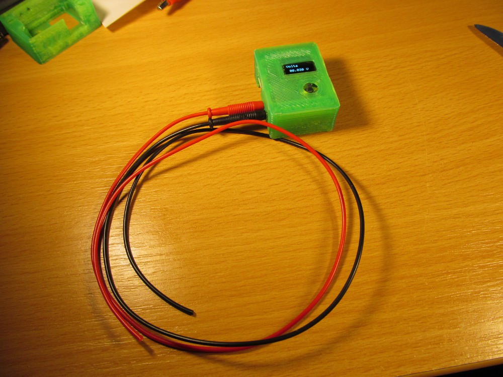
Threaded inserts are in place, waiting for 3D printed cover with M2,5 machine screws (or bolts? not sure about the terminology) and with test probes (with no actual probes attached) it reminds a DMM, somehow
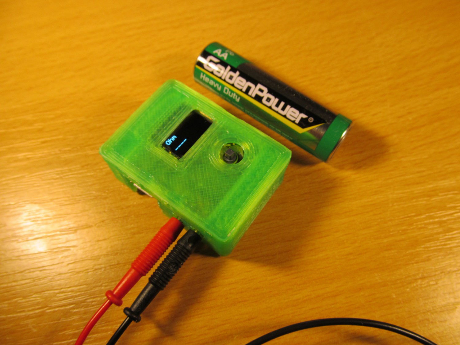
... and with AA battery for scale
So far so good. I need to make final touch to firmware, print the bottom cover for enclosure and finish the test probes.
Discussions
Become a Hackaday.io Member
Create an account to leave a comment. Already have an account? Log In.
Fabulous !
Are you sure? yes | no