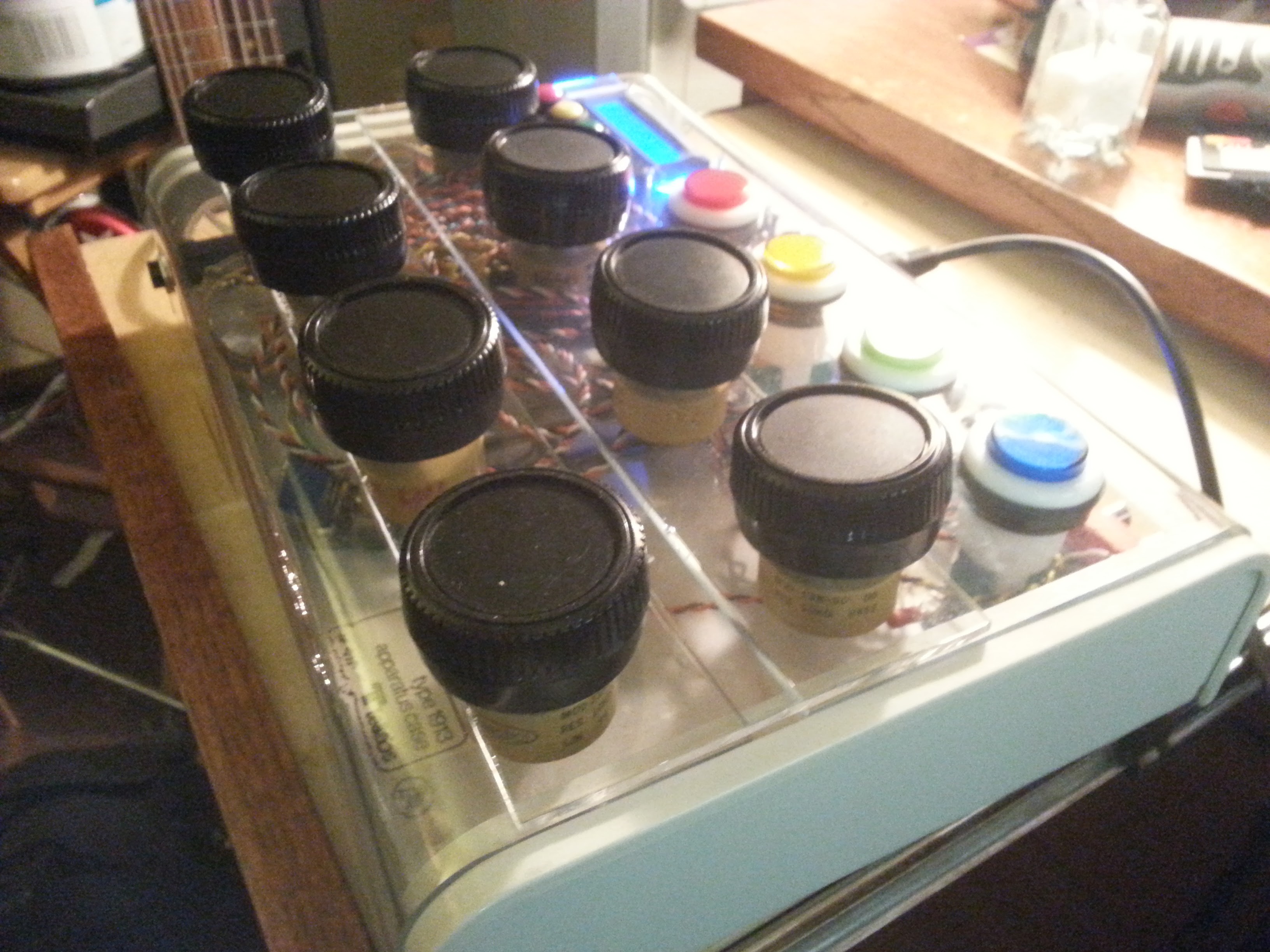
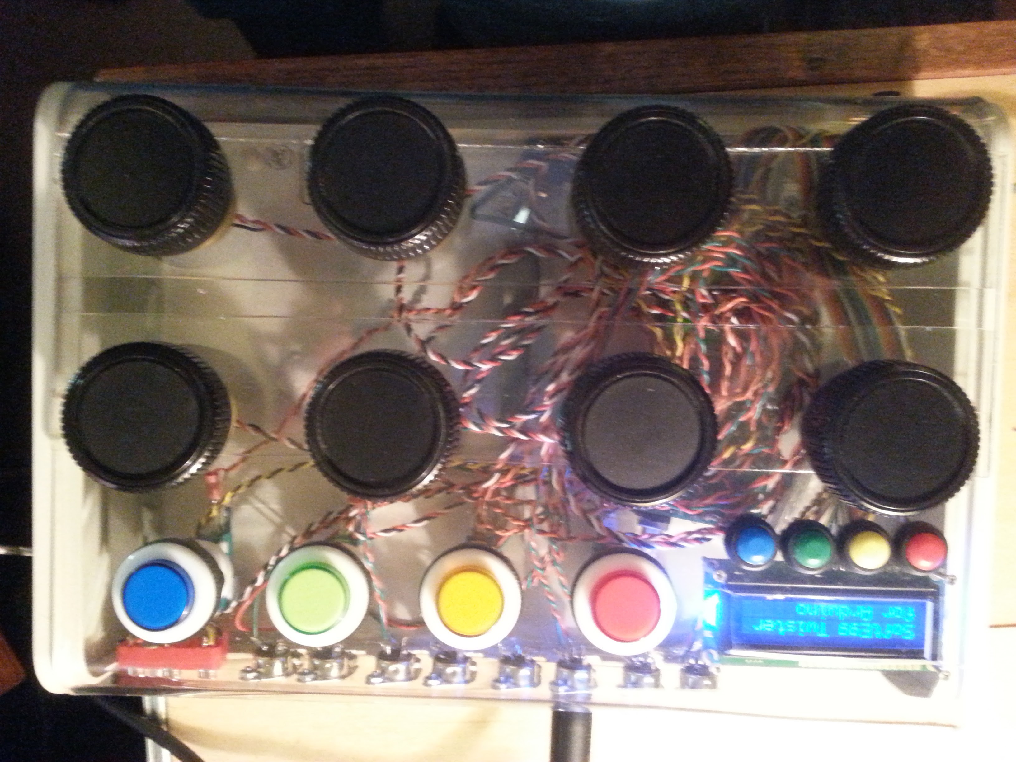
• Debugging Stuck Notes

    T. B. Trzepacz06/09/2016 at 10:17 0 comments

    I was having some peculiar errors playing a keyboard through Twister into the NanoEgg synthesizer prototype. Namely, it would often lose note off commands, resulting in stuck notes. That really sucked, and made for some terrible demos, so I finally decided to sit down and hack through it.

    The initial symptoms:

    1. If the E-MU keyboard is attached to MIDI IN on Twister, and the out is attached to NanoEgg, stuck notes will often result.
    2. If E-MU is attached directly to NanoEgg there are no problems.
    3. If output is from Twister to another MIDI device, no problems.
    4. If input is a different MIDI keyboard, no problems.

    I put lots of print statements in the Twister code, and confirmed that Twister, at least, is receiving and thinks it is sending the correct data.

    And print statements in NanoEgg indicate that it isn't getting the note off.

    Since it worked with a direct keyboard, I assumed that there was an electrical problem. I wasn't in a good place to debug circuit problems, because of a lack of test equipment. I actually own an oscilloscope from my father's workshop, but that vacuum tube beast from 1968 lacks the modern features like waveform capture necessary to really understand what is going on.
    Fortunately my friend Arclight from 23b Shop offered to lend me an oscilloscope to track the problem down. Thank you so very much!

    The first thing I noticed was that the levels from the E-MU seemed to be tremendously lower than those coming off Twister.

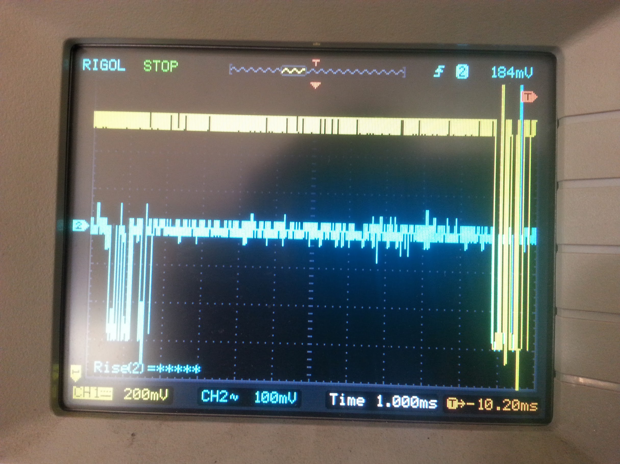
    I had to crank the time resolution way down to determine the lag between input and output, which was 11.18ms . The input signal was only about 320mV, while the output was 1.45V. I started to suspect noise might be a problem, and started to think about biasing the signal higher to avoid it.

    I tried different MIDI sources and different power sources with some crazy results. Here is a Casio portable keyboard using an old Sega Genesis power supply:

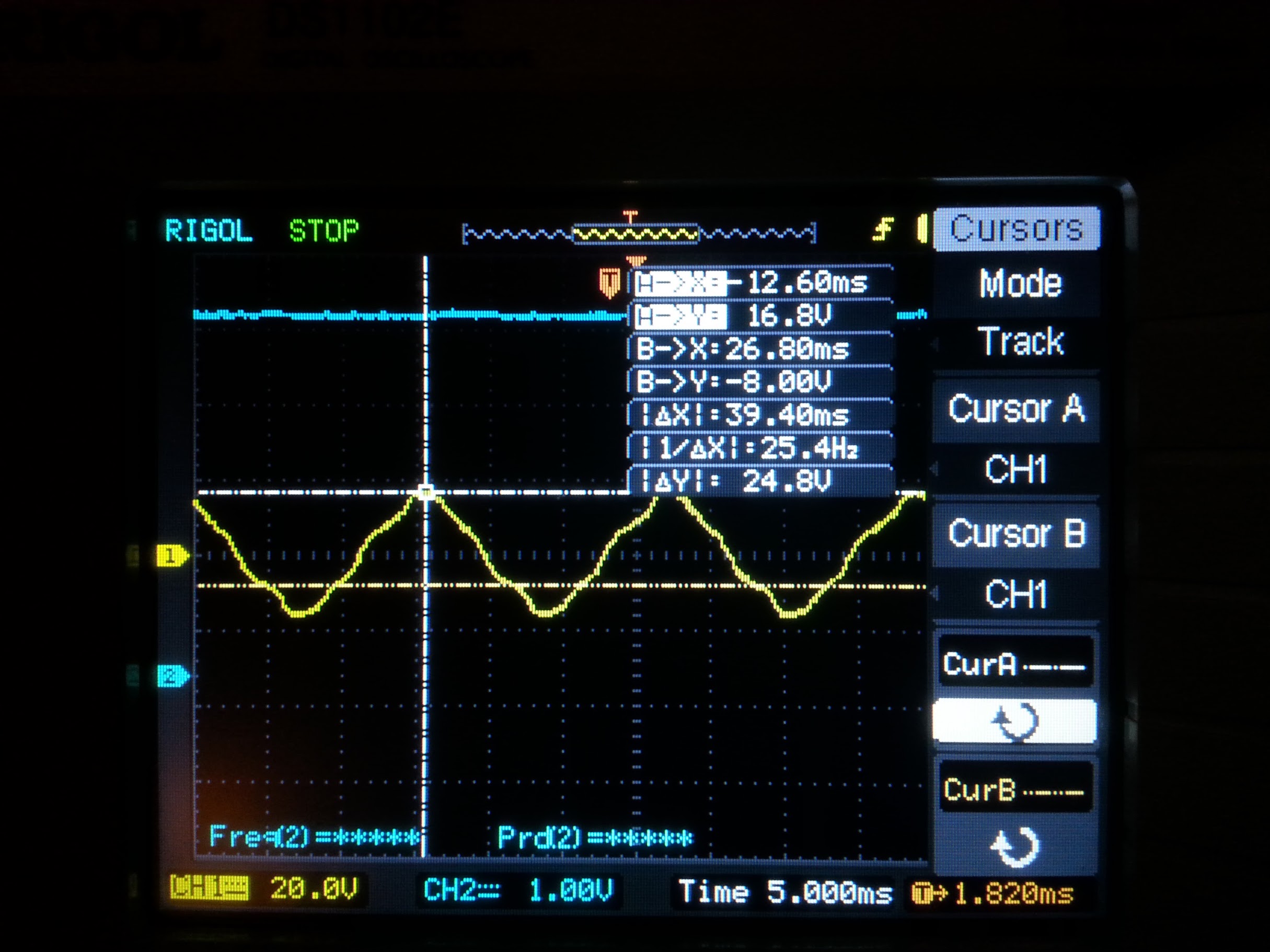
    The power supply is basically leaking 33.6VAC peak-to-peak out the MIDI jack! But it actually doesn't matter, because both pins are getting it so it cancels out in the optoisolator. This is the wonder that is MIDI.

    So, time to do some serious debugging.

    Let's look at the signals and see what we get:

    The E-MU to the Teensy synth works fine, so let's see what that looks like:

    Approximately 280mV peak-to-peak, but the transitions seem clean enough.

    Does it change when attached to Twister?
    No, that looks about the same, and it's fine.

    So, does anything change when we attach the synth?
    No.

    So, what does the output from Twister look like then?

    Some interesting peaks, but otherwise very clean 1V signal.

    So, let's compare the output from Twister to what comes to the RX line on the Teensy 3. This is for the occasion of a note that "stuck" and didn't receive the off command, which is displayed below.

    So, the optocoupler leaves gives some interesting leading edge curves. Is that a problem?

    What does an OK signal look like?

    I'm displaying at a different time base, but it is pretty much the same.

    So, I'm drawing a blank here, but I keep playing with it and I notice that there is a little glitch on the ones where the note got stuck. It turns out that my MIDI keyboard has "aftertouch", where it sends continuous velocity data after the note is hit. Generally there is a threshold and a delay before such data is sent, but on this keyboard it is possible to get it even on a quick key press.

    Aftertouch looks like this:

    Now, I put all sorts of print statements in the Twister code to make sure that it is decoding the aftertouch messages correctly. It is.

    So I tried making sure that it doesn't echo the aftertouch data AT ALL. And that does fix the problem. So it is definitely aftertouch. Probably definitely.

    So I put prints in the MIDI library where it receives and sends the data and confirmed that the data is sent correctly. It is.

    I start looking at the NanoEgg prototype suspiciously: If Twister is doing everything OK, and the problem only exists on NanoEgg, could NanoEgg be the problem, even though it only...

    Read more »

  • It works!

    T. B. Trzepacz05/29/2016 at 10:34 0 comments

    I finally got the knobs to generate MIDI CC output! It turns out you have to send on channel 1 or greater. Channel 0 doesn't work. Perhaps the Arduino MIDI library subtracts 1 from them?
    Anyway, I've got it attached to the SoftEgg Synth, the prototype of the synthesizer engine that will end up in the NanoEgg. I don't have all of the possible CC values set up in the synth software, but I do have about 16 knobs defined, and it works great with all of those.

  • Crashing problems. Time for hardware upgrade?

    T. B. Trzepacz05/23/2016 at 08:55 0 comments

    So, I decided to just do a quick and dirty implementation of the controller with the knobs hardwired so that I could take it to 23b Shop to show to folks, but unfortunately, as soon as I started trying to send knobs over serial, it started crashing hard. I'm not sure what the problem is yet, but I am guessing that I'm overflowing the Arduino serial buffer. Perhaps I am polling the knobs too much?

    In any event, I've been straining kinda hard on the edges of the capabilities of the MEGA 2560 (printing status to the console slows MIDI output down tremendously) and so I started looking at other Arduino alternatives to see if I couldn't make my life easier. As it turns out, there *is* the Arduino Due, which has similar specs to the Teensy 3 in an Arduino Mega 2560 shaped package. Like the Teensy 3, it is a 3.3V device, so I'd probably have to change the values of the resistors on the board, but otherwise it should be able to handle my project easily, without laying out and ordering new boards. Even better, clones can be had on eBay for about $15.

    It seems worth a shot, so I found an experienced seller and placed an order. I won't see them till June (yay, China shipping) but I'm looking forward to having a lot more processor and memory to play with for the Twister project. I even ordered a 2nd board to see how well it handles an implementation of the NanoEgg Synthesizer engine.

    I'm still gonna keep hacking on the Mega 2560 version, but if it works out I might switch to the Due for the release implementation.

  • Coding progress and UI redesign

    T. B. Trzepacz05/21/2016 at 11:46 0 comments

    Finally figured out what was wrong with my Twister MIDI knob box project and got it echoing data properly.

    I decided that I really needed to do a proper UI design for the 4 button and 16×2 character display. I had a concept before, but it really wasn't working out. I think this will be much better.
    It takes 3 button pushes to get to the point where you can reconfigure a knob parameter. Each knob can adjust 3 different things. Adjustments can be Control Change or System Exclusive. SysEx can be up to 16 bytes, although I am not sure how I will handle MSB/LSB yet. Each parameter can have it's own range of values and it's own adjustment curve (like the envelope curves in Rhythm Core Alpha 2).
    I'm also intending to implement MIDI routing and key split between the ports.
    One thing that might throw a monkey wrench in all this is that I only have 8k of RAM in the Arduino to play with, and only 4k of EEPROM to store patches in. Event the16MHz processor seems quite limiting. I may have to scale these features back to fit the hardware and save them for a V2.0.
    I'm starting to consider combining this with the Nano-Egg synth project and building a unified platform PCB that handles the common aspects of both.
    I went to start working on that in KiCAD, but discovered there weren't really comprehensive parts for the Teensy 3.1+ in KiCAD. The tutorials for making your own were from an earlier version that didn't work the same way, so I ended up rage quitting and trying it in Eagle. Eagle does have parts designed for the Teensy 3.1, but also lacks the Teensy audio board. I suppose I'll have to devote some quality time to learning how to make a new part in... some program or another.
    I was doing some research and determined that the Arduino can only do analogRead about 9.1kHz. That doesn't seem great...
    Source: http://meettechniek.info/embedded/arduino-analog.html

  • Early progress flashback

    T. B. Trzepacz05/17/2016 at 07:58 0 comments

    I didn't really start writing about this project here until I'd been working on it for quite awhile already. There were many trials and tribulations just in fabricating the box.

    One of my friends at 23b Shop in Fullerton went so far as to write a nice article about me and my struggles in their blog, which I thought some folks might find interesting!

    http://blog.shop.23b.org/2015/08/n00b-hacks-harder.html

  • No 3d printer? No problem!

    T. B. Trzepacz05/17/2016 at 07:01 0 comments

    The Twister project contains 4 fairly expensive arcade buttons, one of which immediately broke when the front panel went flying off the car seat during a sudden stop.

    I tried gluing and taping it several times, but the results were poor, and temporary.

    I considered 3d printing a new part to hold the switch in, but I don't have reliable access to a 3d printer.

    But I do own a stash of filament.

    And I do own a soldering iron.

    But will it hold the switch?

    Signs point to yes!

  • Stuck notes?

    T. B. Trzepacz05/16/2016 at 08:49 0 comments

    Now that the box is all wired up, it's time to actually write the software. One might think "Oh, the hardware is done now and we don't have to touch it again!"

    But, if you thought that, you'd be wrong.

    Like me.

    No, this is where we actually find out if the hardware is working. Of course, tests were done, but when faced with software trying to do real things, it might turn out a little differently. For example, yesterday I wrote about how the Arduino A/D converters were only accurate to within +/- 4 and we were basically losing the bottom 2 or 3 bits of resolution from our 10 bits giving us maybe 8 bits with smoothing.

    Today, the MIDI ports are the ones being stressed. The intention is that a MIDI keyboard can be played into Twister, and the results routed between all of the output ports, with the control data from the knobs added as necessary.

    Although input is showing ok, output seems to be prone to dropping bytes here and there giving us fairly regular stuck notes when I try to play through it.

    Whatever could cause this?

    Is it a problem with the hardware or the software?

    Time to debug.

    For those of you unfamiliar with the process, debugging generally follows the scientific method:

    1. Form a hypothesis of what might cause the problem.
    2. Perform an experiment to see if that is actually the problem.
    3. Observe results: Yes, that was the bug. No, it must be something else.

    So, let's try a few:

    Hypothesis 1: Problem is input
    Experiment: Print the input to the console and see if it is losing any note off commands.
    Result: No, all the note on and note off commands could be seen in the console.

    Hypothesis 2: Problem is that Arduino is slowed down by printing output.
    Experiment: Remove debug printing of MIDI input commands and see if it works better.
    Result: No. Results were better, but it was still possible to get a stuck note.

    Hypothesis 3: Power supply is insufficient
    Experiment: Attach a 1 amp power supply to the Arduino instead of relying on USB power.
    Result: No change, still get stuck notes.

    Hypothesis 4: The target synth is to blame
    Experiment: Grab another synth and see if it is better.
    Result: Promising. Certainly fewer stuck notes on the Casio than on the breadboard prototype of the NanoEgg synth. The Casio does occasionally seem to trigger a low bass note that has no relation to what is being played, tho.

    Hypothesis 5: This MIDI cable is crap.
    Experiment: Try another MIDI cable.
    Result: Promising. The Casio almost never gets a stuck note now, but the NanoEgg prototype still sticks all over the place!

    Hypothesis 6: USB power from PC hub is insufficient on the NanoEgg prototype.
    Experiment: Try using an external USB power source.
    Result: No change. Not the problem.

    Hypothesis 7: Knob reading code makes it slow.
    Experiment: "Comment-out" (temporarily remove) knob reading code.
    Result: No change. Not the problem.

    Hmmm.

    So some improvements have been made, but it still is rubbish at sending MIDI through to the NanoEgg prototype, which is kind of the point of this project. Certainly, the breadboarded prototype of the NanoEgg is going to be more susceptible to electrical noise, but it seems rock solid when played directly from my MIDI controller, so I feel like something else is going on. Is the MIDI out circuitry on the Arduino not as robust as it should be? (It's just two resistors attached to the connector, one to 5V, and one to TX, with a capacitor between 5V and ground.) Or is there electrical noise on the line inside the ratsnest of wires inside of the Twister box?

    This seems like a good point to take a break and consult with some other folks to see if anybody has any ideas.

    Edit: I came back to it after a bit and noticed something strange. Controls I didn't wire up, like the pitch wheel, are working. So I commented out all the code that is supposed to echo MIDI to the output, and MIDI is still appearing at the output. But only if I call midi.read(). So that means the connections aren't somehow bridged, but that the MIDI library is echoing on it's own?
    I'm very confused....

    Read more »

  • Arduino analogRead Averaging (and Alliteration!)

    T. B. Trzepacz05/15/2016 at 10:11 0 comments

    So, even with my very expensive precision potentiometers, using "analogRead" on the Arduino has the values varying as much as +/- 4, reducing our 10 bits of resolution down to not quite 8 on a good day. What to do?

    Well, when I had similar problems reading resistive touchscreen on the Teensy 3, I had some success eliminating noise by taking the average of 4 consecutive reads. So I tried that here:

    #define NUM_KNOBS (8)
    int knobValues[NUM_KNOBS];
    
    
      for(int i=0; i< NUM_KNOBS;i++)
      {
        int value = analogRead(i) + analogRead(i) + analogRead(i) + analogRead(i);
        value>>=2;
        int delta = abs( value - knobValues[i] ); 
        if ( delta > 2 )
        {
          knobValues[i]=value;
          Serial.print(i, DEC);
          Serial.print(" ");
          Serial.println(knobValues[i],DEC);    
        }
      }
    I unrolled the loop of analogRead, and used a right shift to do a divide by 4 to save cycles. As long as you are averaging powers of 2, that is the best way to do it.
    I managed to increase the accuracy by about +/-2 this way, which gives us maybe a single bit of resolution back?

    I upped the averaging to 8 values ( which has to be getting kinda slow by now) and got it stable to +/- 1!
    For grins, I upped the averaging to 16 values, but it didn't increase the accuracy enough to be useful, and 8 seemed to still have some stability problems, so I backed down to 4 again.

    I worry that, since this thing is supposed to also do a bunch of other MIDI stuff, that I might be slowing down everything else, so I might have to back off on the averaging eventually, but for now I'll leave it at 4.

    Another problem is that the knobs don't seem to cover the full voltage range. Some don't go all the way to zero. Some don't return analogRead values higher than 1015 (out of 1023).

    While one could determine the limits of each pot and subtract and then scale the values accordingly, that isn't really feasible for a production unit. Instead, the best bet is to find the maximum deviation at each end, and clamp that off and then scale across the range (or cut off some bits if that is more convenient....)
    The highest minimum value for a pot seems to be 9. The lowest maximum value for a pot seems to be 1012.

    So to spread the values across the range we

    1. subtract the highest minimum value ( 9 )
    2. multiply by the desired maximum value ( 1023 )
    3. divide by the range of values (highest min - lowest max) ( 1012 - 9 = 1003)

    But this will give us some odd values if the value is less than 9 or greater than 1023. That is easily resolved with some if tests.
    Multiplying by 1023 is silly when 1024 is just a left shift by 10. But we want to make sure the output value won't exceed 1023. Now we are going to clamp ANYWAY, but it would be nice to squeeze out as much range as we can, so we should determine how high our divisor needs to be to get 1023 from an input of 1012 instead of getting 1024 at that value.

    Hmmm. Can't really do integer math with values less than 0. Well, let's try calling it 1 and see what we get.

    Well, that's great if we have rounding, but in integer we don't, really. So clamping it is!

    Note that we are multiplying a 10 bit number by 10 bits, which means we need 20 bits for the result! This will not fit in the 16 bit math that is default on Arduino, so we have to explicitly define our work variable as 32 bits using the "int32_t" type.

    #define HIGHEST_MIN_VALUE (9)
    #define LOWEST_MAX_VALUE (1012)
    #define VALUE_RANGE (LOWEST_MAX_VALUE-HIGHEST_MIN_VALUE)
    #define MAX_RANGE (1023)
    
          int32_t outval = value - HIGHEST_MIN_VALUE; //note: 32 bit math!
          if ( outval < 0 ) outval=0;
          outval<<=10;
          outval/= VALUE_RANGE;
          if ( outval > MAX_RANGE ) outval = MAX_RANGE;
    
    This means that there is a little bit of play in the values at the beginning and end of the range, but at least we can reach 0 and 1023 reliably now. If we wanted to get fancy, we could store a min and max value for each knob and expand the range on the fly, but why waste the cycles when this is good enough?

    This also means that it is not possible to get every single value. It is going to skip some....

    Read more »

  • Making the knobs fit

    T. B. Trzepacz05/15/2016 at 08:31 0 comments

    The knobs I chose for this project are very special: they are knobs from the original Atari 2600 paddle controllers! I bought them at All Electronics in Van Nuys many years ago, and there probably won't ever be a way to source them again. The prototype of Twister is a one-off!

    It was really hard finding potentiometers that would fit the holes in the knobs, and even the rather expensive pots I did find had rather short shafts. The plastic knobs have metal bits inside to grip the shaft, but they are shoved too far up to work on these pots, and they ultimately get in the way.

    So I chiseled them out with a screwdriver and wrapped the shafts with blue painter's tape until the knobs had a good friction fit.

  • It's Alive!

    T. B. Trzepacz05/14/2016 at 10:50 0 comments

    Twister is finally all wired up! And it works! There are still some kinks to work out, however:

    • I didn't realize that Arduino doesn't have a separate serial for the USB, and so the first MIDI port and the USB can't be used at the same time.
    • One MIDI Input port of the 4 seems non-operational.
    • A row of buttons wasn't working. I tested the board and the connections seemed fine, but soldered an extra wire to double that connection and it now works. Go figure.
    • The headphone jack turns out to be mono, and so I will have to wait to wire it up until I have the right connector.
    • The pin headers add a LOT to the height of the Arduino + Shield assembly, the wires even moreso, and it will no longer fit behind the display. The USB and power connectors will have to be relocated if they are to be accessible.
    • The USB port on the Arduino Mega 2560 rubs up against the bottom of the shield board.
    • The A/D lines are supposed to be 10 bit precision, but the value seems to waver by +/- 4, and so really there is only barely 8 bits of precision on them. My grand idea of sending sysex with greater precision values seems less possible now. 8 bits is more than the 7 that MIDI can send in a CC message, but only slightly.
    • I forgot to make a mounting hole for the screen contrast adjustment potentiometer.
    • Crimping pin connectors sucks. I never want to do that again.

    Still, it works. I'll definitely work to get the mounting ironed out and write the software to run it now. I'll probably want to iterate on the design tho. Too bad I've still got 4 of these printed circuit boards left.