 Yann Guidon / YGDES
This is a sub-project of #Grimoire
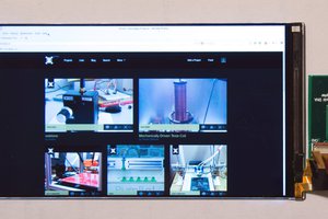
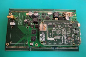
Logs:
1. Bill of Material
2. First shots
3. Analog frontend
I need your help to develop the smallest and cheapest (yet useful) breadboard sniffing tool!
Already have an account? Log in.
To make the experience fit your profile, pick a username and tell us what interests you.
 twl
twl
 Greg Duckworth
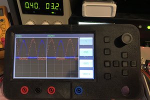
 Lucy Fauth