Close
0%
0%

A-Hen-Ho

Automation of the hen house. Light, door, temperature tracking. Using Raspberry PI as main unit and Wi-Fi as connection-configuration link.

Similar projects worth following
A few days ago one of my friends asked me about automating his hen house. The winter is coming and he needs to extend a light time for the chickens. So the device should switch on/off the light inside of the hen house in the appropriate time. Plus as every lazy guy he don't want to wake up every morning at 6 am. and go to open the door of the hen house to release the chickens and let them walk around. Additionally he wishes to have a possibility to supervise the temperature inside. The distance from home approx 60 - 100m and he wants to manage everything from his home. The project seems to be not complex and really difficult. But as one more combination of known solutions, can be taken.

First of all the connection from home to the hen house will be done by a Wi-Fi. Configuration and supervising will be done from a convenient web-interface.

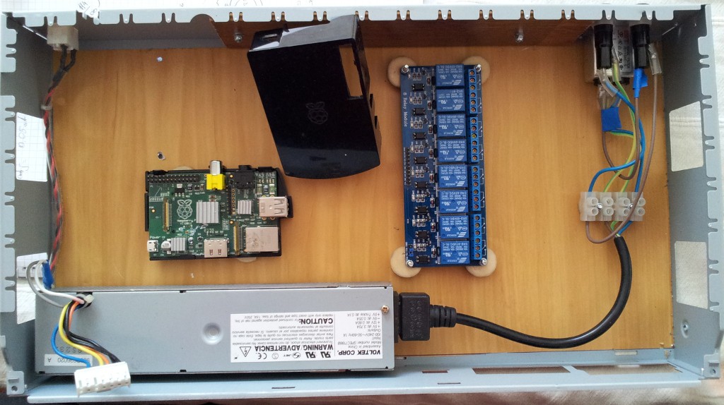
Raspberry Pi + Raspbian + NodeJS + Meteor/Angular/etc. (?)

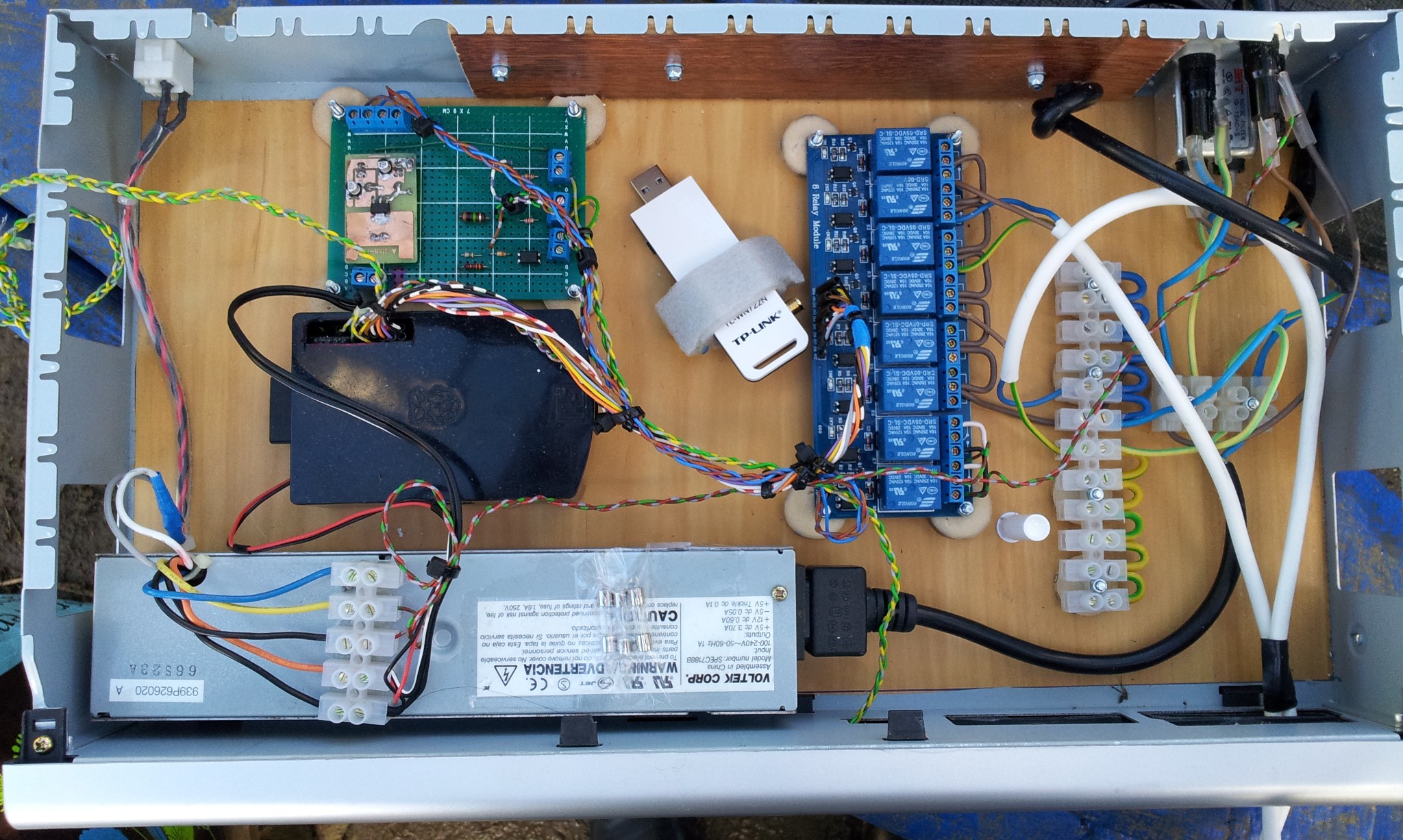
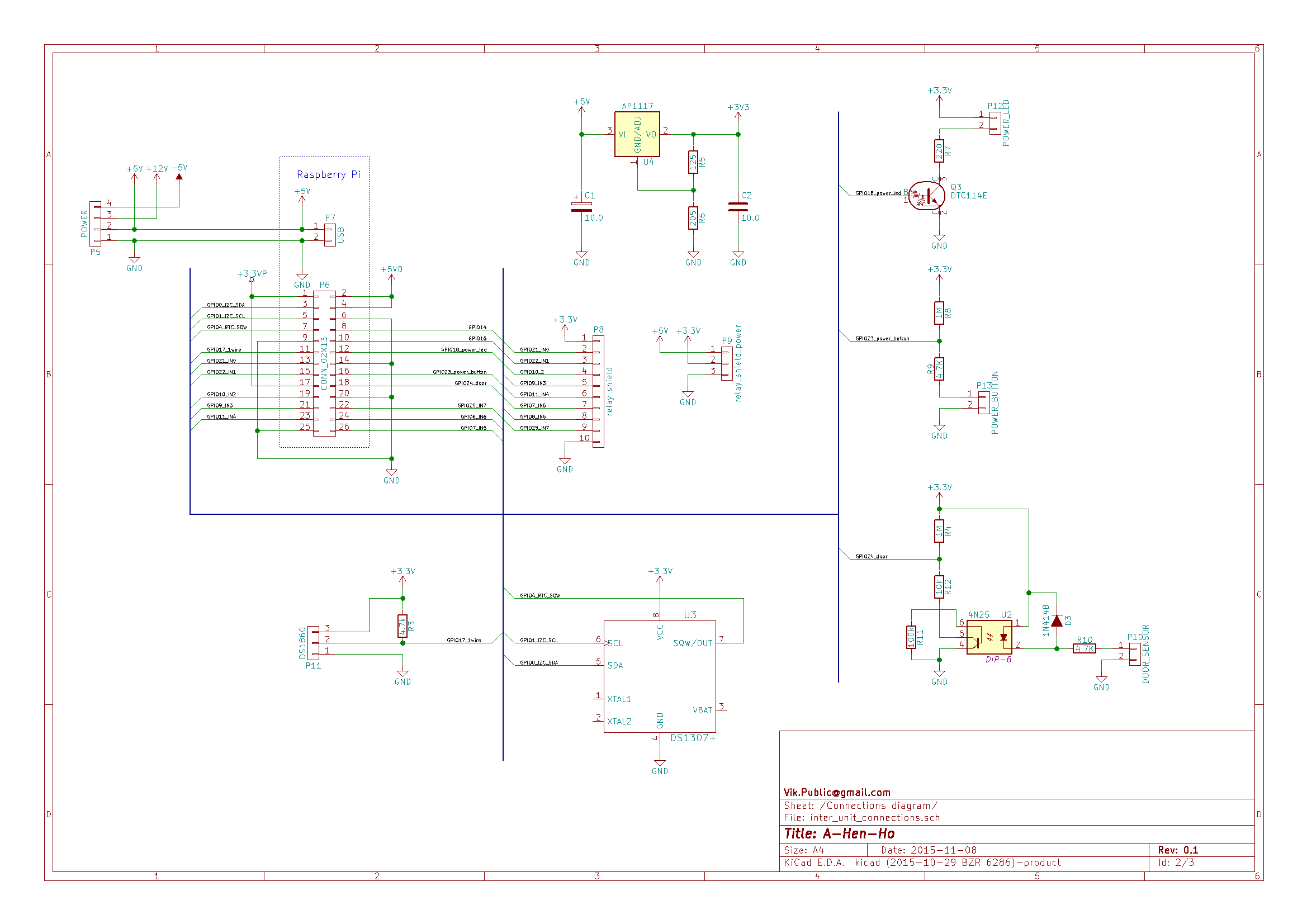
To switch on-off the light, to open the hen house dor in right time I will need a RTC clock. The Raspberry Pi itself have neither RTC clock no BIOS chip with battery backup. So the RTC should be external and I have few of those nice DS3231 modules with RC2032 battery socket, which can operate from a battery up to years, have internal calibrated quartz crystal, programmable crystal calibration, and many other nice features. I2C connection supported by the Raspi. I'm awaiting that DS1307 i2c kernel module from raspbian will do a job without huge configuration. there is a short HOWTO and many other links: link1, link2, link3, link4.

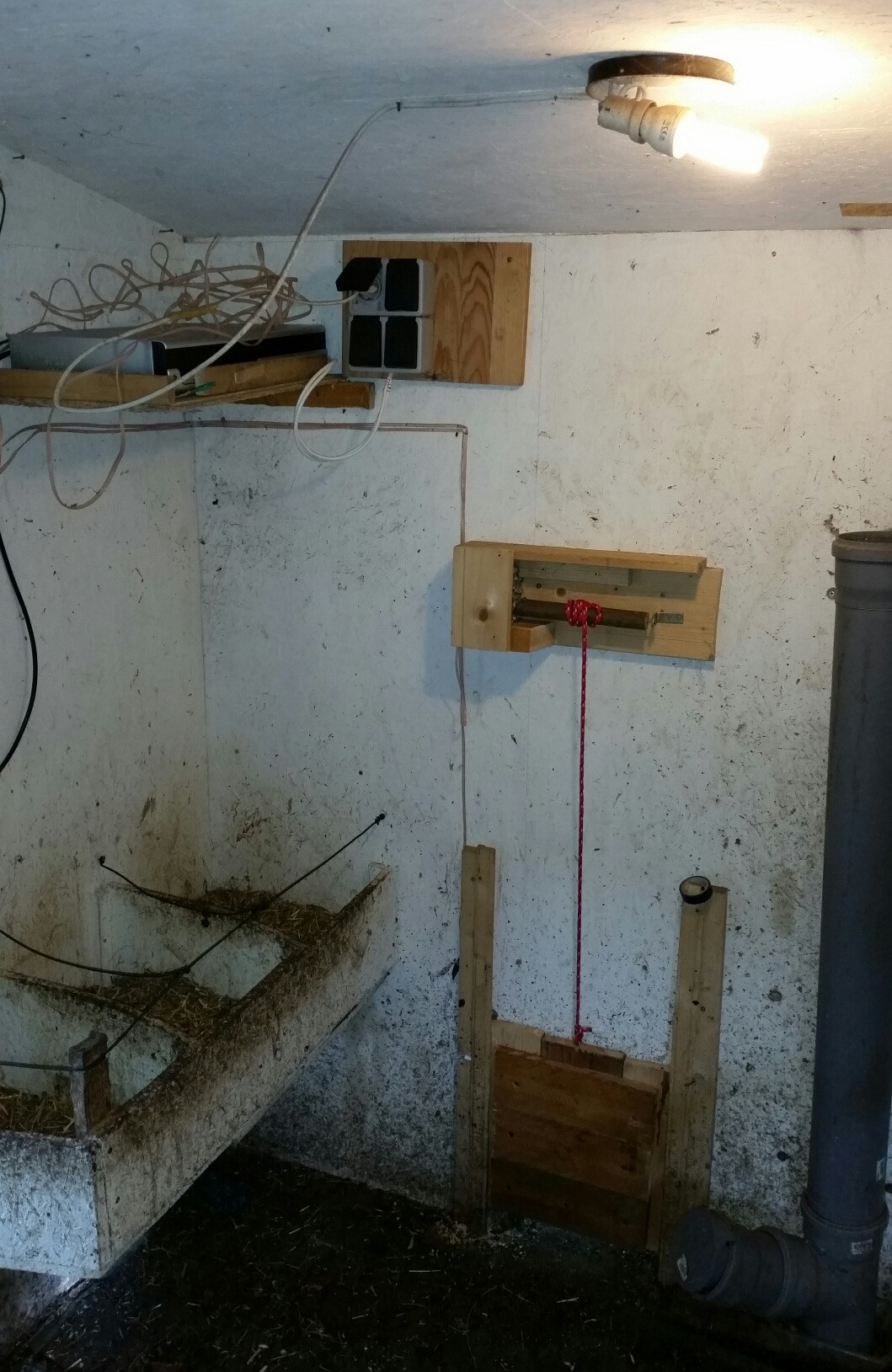
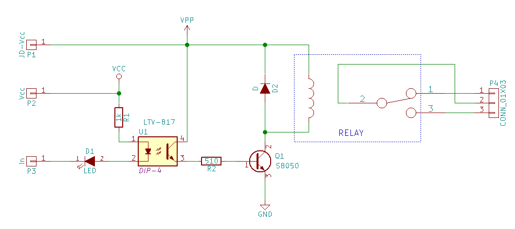
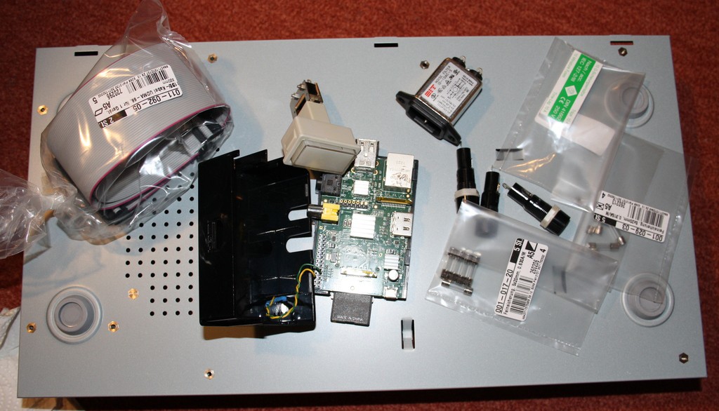
To open a door I will use a 12V motor with a reduction. According to my measurements it takes 0.2 A to operate.

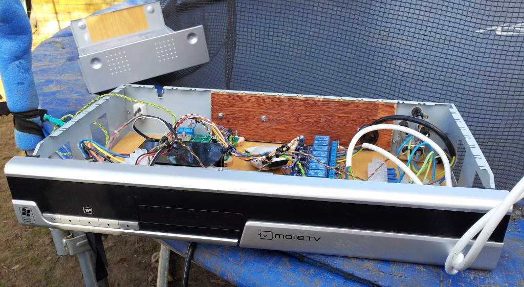
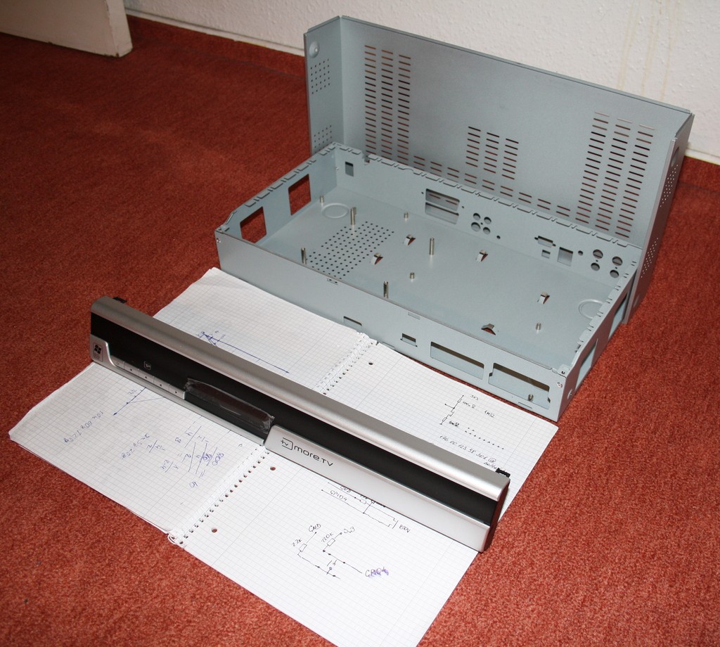
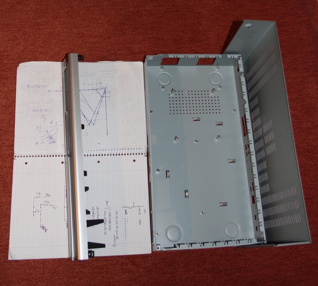
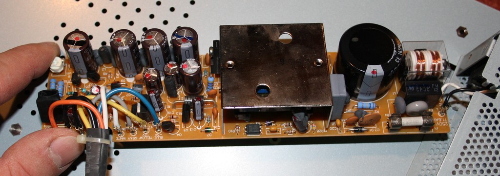
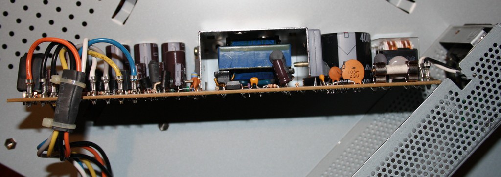
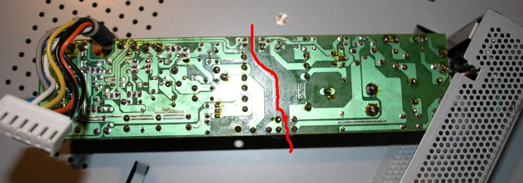
That is why I will use power supply, which provides 5V/3.7A + 12V/0.6A. Ideal combination. Unfortunately not dust protected body, but I plan to put everything in the big enclosure. The dust and humidity problem will be solved there.

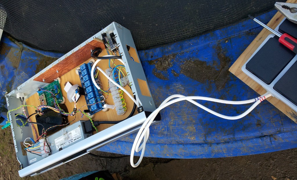
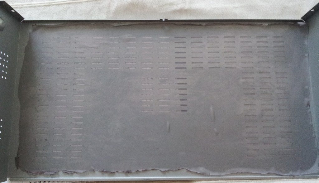
Protecting everything against dust, humidity, trash, chickens :) is an important topic of the project. The device used to function in the hen house, which is not warmed, not really closed, have a loooot of trash in the air and everywhere. And working 365 * 24 with very rare checking and supervising means, that everything should be really safe.

Project should be complete until middle of december 2015

All the code for a project is available on GitHub::A-hen-ho

View all 15 components

  • Done!

    vik.public06/27/2016 at 10:29 0 comments

    It's done. Thanks for following :). See you on the next project.

  • Done?

    vik.public03/05/2016 at 11:22 0 comments

    Ok. The project is almost done. All software changes are checked in github, hardware works stable. I've sent it to a place where it will do it's job. And it will stay there forever, if everything will be fine. The owner of the hen house promised me to send me a report about installation and functioning of the device.

    Some results, notes and expectations:

    Achieved goals:

    1. Device exists ))

    2. Device have 8 channels to manage. each channel is isolated from raspi and capable to switch in theory 220V x 10A. Which is much more than needed.

    3. Each channel is compatible with an energy saving lamps

    4. device can operate without monitor/console/terminal on the field. it has power-off button and a web interface. WiFi configured as AP

    5. device is ignorant to main power fail-off's. by default it switches on on the power on situation. the time is tracked by RTC unit and RTC unit has independent backup power supply based on rechargeable battery.

    6. device has minor dust protection

    7. a door sensor, which is connected by a long wires has an optical isolation. not really proper, but can help in advice.

    Notes:

    I've used a Raspberry Pi B (rev 1) there. There is no reason for something else. Yes it is slow, probably rev.2 can be used. but it is not really important. Any of the Rasi's can be used there and many other single board computers. But. I definitely need USB port for WiFi. The WiFi embedded in Raspi rev 3 will not do a job because for this project was really important to have a WiFi with external and exchangeable antenna. We tried some antennas and now plan to use directed antenna with 25 dB amplification. Plus antenna must be taken out of the steel case and placed outside the hen house.

    The start plan was to use NodeJS and Motor for web interface. But investigation this topic I've found that NodeJS on raspberry pi is slow, Mongodb (used by Motor) on raspberry pi is very slow. the Motor is extremely slow too. And even start Motor on the Raspberry PI is almost impossible, because it uses some native code, which is problem to compile on RPi. Using a Python + flask + AngularJS solved all these problems. I don't think that stay on the plan with NodeJS was a good idea and really like the way project done now.

    Replace RPi there with some other modules, like ESP8266, STM32 etc. Probably bad idea either. ESP itself can't manage direct signal 8 channels + RTC. It will need some 74xx chips additionally, or STM32/Atmel/PIC as a main unit. The second point is a web interface. It needs a lot of memory. for a moment it uses angular.js + some custom scripts + styles + bootstrap.js and a web-server. My expectation about size of all this code is approx 1Mb, or more. this means, main unit should be really powerful. managing of the RPi is much easy than managing of the controller-based system. at least I know, how I can make updates/fixes etc. And it comes out of the box.

    Expectations:

    Everything should work fine. After first testing on the place I wouldn't expect any huge trouble. But there still some unpredictable factors, like ammonia, or any other chemical stuff in the air inside the hen house, where the device will be located. chemicals, humidity can spoil something in soldering, case or in wires. in any case the fuses on the entry should protect against fire and steel case should take part in the protection.

    Anyway. I'm waiting for news from a filed.

  • Fixed

    vik.public02/21/2016 at 17:46 0 comments

    Yes, the diode was failed. U'm not sure, that 1N4148 is a good choice for this job. It's too weak probably. I've replaced it with 1N4003. Problem was solved. I'ev added some additional code to check the situation with failed events in the scripts.

  • Stability problem

    vik.public02/19/2016 at 11:35 0 comments

    I did a lot investigations about this problem last days. It looks like device goes to a correct shutdown after I' switching on/off relays. Not every time, but with a high probability.

    The first idea was - initial value in the GPIO register. Need to say, that almost all the logic of the GPIO operation in this device is inverted. Relays are off, when appropriate pin is in the high state. the door and power buttons are waiting for falling edge in the input signal. but on boot-up time, all the values in the RPi value registers are initialized with 0. This makes switch ON-OFF pulse on the time when I'm changing the GPIO pins mode from initial Z-mode to OUT. Looks it like this: after boot-up all the pins in Z-mode, the signal LEDs on the relay shield slightly on, but not enough to switch relay on. after I'm changing mode of the GPIO pin to OUT, relay shied switches ON and then immediately OFF. There is a pulse. My idea was that this pulse leads to the false event detection of the power button.

    the problem was solved by setting boot sequence: switch all the pins to OUT, set low values to the pins used as inputs and high values for other. switch necessary pins to IN mode and start waiting the event. This makes things better, realy shield LEDs became looking proper, no switching pulses anymore, but switching relays on-off still causes a shutdown and false events on the power button. As alternative I've start using some python RPi.GPIO class options:

    to init pin input pull-up resistance (didn't knew about these - this could made my schematics bit simpler):

    GPIO.setup(channel, GPIO.IN, pull_up_down=GPIO.PUD_UP)

    to init a value before changing PIN mode to a OUT

    GPIO.setup(channel, GPIO.OUT, initial=GPIO.HIGH)
    

    both tricks were taken from RPi.GPIO module documentation page

    but I've continued my investigations. I had a way in mind to disable sensing a signals at time of the relays switching, but don't really want to implement this, while it will require synchronization between different processes in the system, or composing all the code in one huge binary responsible for everything. I even tried to skip the distortion using

    GPIO.add_event_detect(channel, GPIO.RISING, callback=my_callback, bouncetime=200)

    'bouncetime' option. Had no success.

    But yesterday I've found that the one and only one relay on the shied do this distortion. And on this weekend I will check again this channel.

    the D2 is under suspicion. At least the channel will function even if this diode is broken, but will make a power line distortions exactly like I have now. I'm crossing fingers )

  • Field tests

    vik.public02/19/2016 at 11:09 0 comments

    It's probably right time to update status quo of the project. In short: a-hen-ho was built more or less in time, but there were some problems, which became visible on the field and I've taken the device back to fix them. Some images from the testing time:

    As one can see, there is a lot of free space inside the case. Probably it would be possible to put all the stuff in the smaller case, but... this one is so solid and properly done, that i'm not in the mood to change it. Another reason - easy access to all the modules and convenient work at all.

    The device place is a shelf inside the hen house on the right corner. for this reason we were forced to make some changes: the power cable was connected through the hole on the case back side, while it is not so much space between the back side of the case and hen house wall. There is no space for a power connector. This is why we've connected 220 line missing the input filter. For a same reason, the power sockets were taken from a front panel. this way is shorter and more convenient. I know, that probably have one common pole wire for all four sockets isn't good idea, but we are not expecting a big loading there. (some energy saving lamps). acceptable.

    the changes I did already:

    Relay shield.

    I've connected it as I explained, Vpp became +5V from a power supply, Vcc is a +3.3V from my external LDO. Raspberry Pi just manages level on the In pins. The first thing which I found is that 3.3V from RPi can manage only 3 relay channels from 8. The reason of this problem was hard to find: all the components looks really good and no one was broken. The fail was in the input circuit - the current was not enough to switch optocouple ON. As solution I just soldered resistances in parallel to R1, reducing it's value to approx 330 ohm. technically by putting additional SMD resistances on the top of the R1 and soldering them together (I hadn't proper resistances to just replace R1).

    The thermo sensor was soldered just to the RPi gpio, because it will measure temperature just nearby the case and it was no plans to take it off for a long distance.

    Problems found in a field test:

    - The omnidirectional antenna with 8 dB is not enough to get a proper connection in our case. Connection to the device was not stable.

    - Stability of the system. After the first light switch on, the system goes to the shutdown with a high probability.

    because of this and because of the not completely done WEB interface, I was taken the device back to a home.

  • Schematics

    vik.public11/08/2015 at 19:59 0 comments

    There is approximate schematics of the interface board. As far as RPi can't supply properly external hardware from it's on-board 3.3V LDO, I have to make my own supplied from a powerful 5V line. DS1820 will be connected using 3.5 jack connector, the pull-up resistance placed inside the case. Power-off button will be inside the case, no real protection needed. Power-on LED is connected using transistor to take as less as possible power from a RPi and at the same time to offer enough current. Door lock-open sensor will be connected using wires of the undefined length. This is why I will do a protection of the input. I think just transistor will not be enough. Both input buttons should connect ground to a input circuit. I think it is more safe, than connect a voltage line.

    Only two GPIO left free...

  • Update

    vik.public11/08/2015 at 12:12 0 comments

    So. Approximately a week passed by since the last log post. I like to update the project state.

    First of all. I did some mechanical stuff with a case.

    The top cover was protected agains the dust with a textile glued on the internal surface. 100% syntetical material was chosen to avoid possible decaying.

    Then I covered the bottom of the case with a vinyl foil to cover all the holes there. And placed some modules already. On the picture you can see the input power socket, fuse holdes, power supply, Raspberry PI, relay shield installed.

    I want to use native case for raspberry pi, while it is a first generation of it and it have no mounting holes on the pcb. so it is quite tricky fix it somewhere. case solves this problem, plus adds additional dust protection. I did a hole in the raspi cover with a Dremel tool to let me lead wires from inside.


  • Relay shield

    vik.public11/01/2015 at 19:13 0 comments

    for everyone, who is interested in the relay shields sold by aliexpress. This is schematics of the one channel. Normally Vcc and JD-Vcc are shortened by a jumper. but it's obvious, that Vcc should be 3.3v for raspberry PI and most of the microcontrollers supplied by 3.3V. And JD-Vcc is a voltage of the relay operation and probably should be at least 5V for proper function. Be careful. Raspberry PI don't allow 5V on it's GPIO!

  • Power unit

    vik.public10/28/2015 at 20:10 0 comments

    DIssapointment of the day: the power source requires not a button, but a switcher with a fixation to be switched on. The idea to use the same button to switch device on and then power linux off dissapeared. I definitely want the button, which will make a signal to the linux to shutdown.

  • First delivery. First impressions

    vik.public10/27/2015 at 22:37 0 comments

    Got a case and other parts from a shop. Here they are

    • The case:

    it is a little bit smaller as 2 sheets A4. made from steel. very solid. with a plastic face, but a lot of holes. I'm thinking how to close it from a dust. The screw pins on the bottom side are on wrong places - I will need to drill them out.

    • The power supply

    a very critical component of the system. that is why I disassembled and checked it by own eyes. The quality is acceptable. The transformer is shielded. The red line is a border between 220V and low voltage parts. all electrolytic caps are for 105 C. and for 10V voltage in the low part. EMI filter on the input. no not-filled holes on the PCB. Some additional soldering on the 5V/4A bus. Schematics for supply less than 50W acceptable.

    • Other parts

    raspi, fuses, fuse holder, input 220V/10A socket with a filter, a button with two LEDs.

    The power supply is normal PC power supply, which requires short the signal circuit to start it up. That is why I bought a button without fixation, but switching contact lead me to the dram, that it would be possible to switch on / switch off the raspi with this button. I need to think about, but have a feeling, that it is possible.

    That is all for now. I will do a layout, how to place all the components inside the case. Unfortunately the relay shield is awaited later, but I will leave enough space for it. Probably will start to do placement and mechanical work on this weekend.

View all 11 project logs

Enjoy this project?

Share

Discussions

Similar Projects

Does this project spark your interest?

Become a member to follow this project and never miss any updates