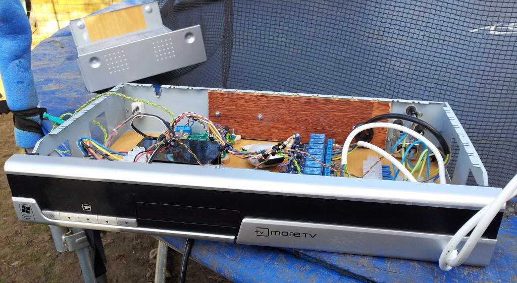
It's probably right time to update status quo of the project. In short: a-hen-ho was built more or less in time, but there were some problems, which became visible on the field and I've taken the device back to fix them. Some images from the testing time:
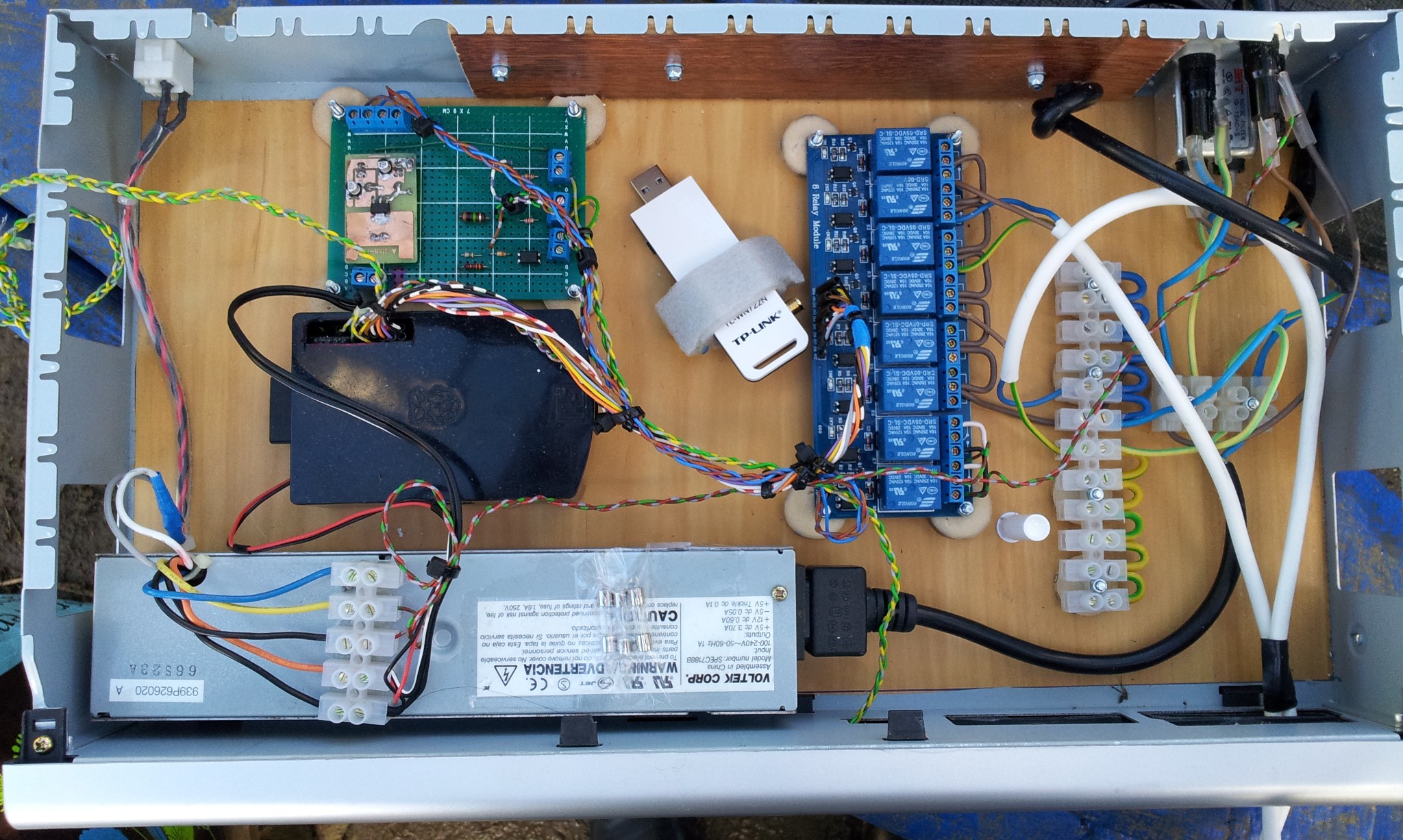
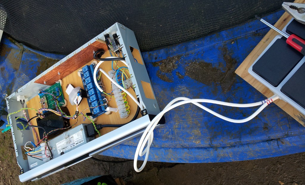
As one can see, there is a lot of free space inside the case. Probably it would be possible to put all the stuff in the smaller case, but... this one is so solid and properly done, that i'm not in the mood to change it. Another reason - easy access to all the modules and convenient work at all.
The device place is a shelf inside the hen house on the right corner. for this reason we were forced to make some changes: the power cable was connected through the hole on the case back side, while it is not so much space between the back side of the case and hen house wall. There is no space for a power connector. This is why we've connected 220 line missing the input filter. For a same reason, the power sockets were taken from a front panel. this way is shorter and more convenient. I know, that probably have one common pole wire for all four sockets isn't good idea, but we are not expecting a big loading there. (some energy saving lamps). acceptable.
the changes I did already:
Relay shield.
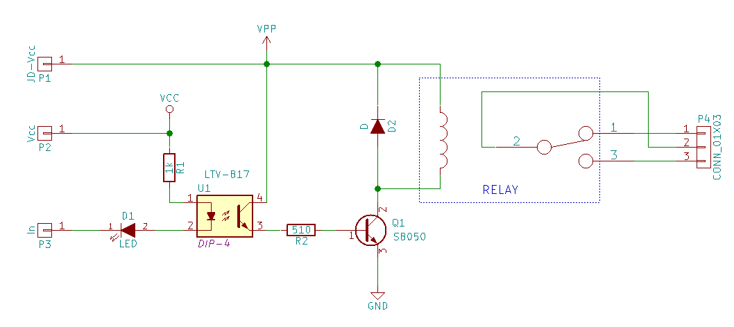
I've connected it as I explained, Vpp became +5V from a power supply, Vcc is a +3.3V from my external LDO. Raspberry Pi just manages level on the In pins. The first thing which I found is that 3.3V from RPi can manage only 3 relay channels from 8. The reason of this problem was hard to find: all the components looks really good and no one was broken. The fail was in the input circuit - the current was not enough to switch optocouple ON. As solution I just soldered resistances in parallel to R1, reducing it's value to approx 330 ohm. technically by putting additional SMD resistances on the top of the R1 and soldering them together (I hadn't proper resistances to just replace R1).
The thermo sensor was soldered just to the RPi gpio, because it will measure temperature just nearby the case and it was no plans to take it off for a long distance.
Problems found in a field test:
- The omnidirectional antenna with 8 dB is not enough to get a proper connection in our case. Connection to the device was not stable.
- Stability of the system. After the first light switch on, the system goes to the shutdown with a high probability.
because of this and because of the not completely done WEB interface, I was taken the device back to a home.
Discussions
Become a Hackaday.io Member
Create an account to leave a comment. Already have an account? Log In.