 Tyler Anderson
The round table where object will be printed on. It is driven by a stepper motor and a large round gear, so it can move both directions clockwise or counter clockwise. This round table is approximately 320 mm in diameter. Rollers around the perimeter support the weight of the platter and keep it level.
The gear ratio for this axis is 385:18. In order to maximize the resolution of the printer, the gear was made as large as possible while still leaving room for the drive motor. For each increment that the stepper motor moves, the platter turns 0.084°.

The radial movement component which functions to move the four extruders. Each sub-component is driven by a stepper motor and a protractor gear. It swings the extruder in and out while printing.
The gear ratio for this axis is 450:18. This allows it to match the resolution of a RepRap (0.2 mm / step).

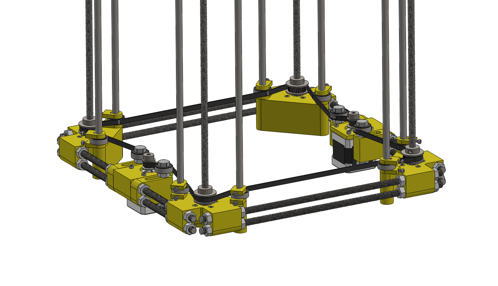
The z-axis component which will be used to move the entire middle section up and down. It has four-threaded rods at the corners. Those rods are synchronized by a timing belt which is driven by two stepper motors. The rods are also threaded into nuts in the middle section. As the rods rotate, the nuts are pushed up or down.
The smooth rods are 8 mm in diameter. The middle section connects to these rods with LM8UU linear bearings. The threaded rods are M8x1.25. They are driven by the timing belt with 36 tooth gears.
Discussions
Become a Hackaday.io Member
Create an account to leave a comment. Already have an account? Log In.